Evaluating a line defect requires controlled repeatability checks, alignment mapping, and elimination of host-side or optical artifacts. The goal is to separate true panel/drive abnormalities from integration-induced effects so IQC decisions are consistent and supplier feedback is actionable.
A true line defect typically stays in the same pixel position across test patterns and normal viewing angles. If the “line” changes with angle, lighting, pressure, or mounting torque, it may be an optical or mechanical artifact. Confirm repeatability, map alignment to the pixel grid, and retest on a known-good reference setup before calling it abnormal.
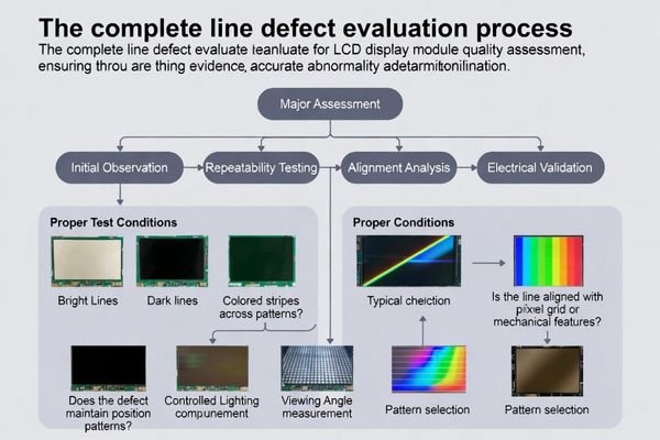
Line-like symptoms can originate from multiple places: the panel’s row/column drive, bonding and interconnects, interface timing and signal integrity, mechanical stress, or optical stack effects. Because different causes require different corrective actions, the fastest path to a reliable conclusion is a structured, evidence-based workflow1.
A practical abnormality decision should be based on what you can reproduce and document: whether the line is fixed to a pixel location, whether it persists across patterns and conditions, and whether it remains when the module is tested on a controlled reference system.
What counts as a "line defect" on an LCD display module?
Line defects are visually continuous linear artifacts that maintain consistent direction and characteristics across the display active area under controlled viewing conditions.
A line defect is a continuous linear artifact—vertical or horizontal—such as a bright/dark line, a color-shifted stripe, or a line of pixels that appear stuck, missing, or mis-driven. It may be full-height/width, a segment, or intermittent under specific content, temperature, or brightness conditions. Define the symptom precisely before judging abnormality.
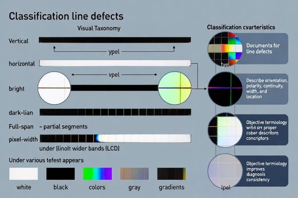
For IQC and supplier communication, a “line defect2” should be described in objective terms: orientation (vertical/horizontal), polarity (bright/dark/color shift), continuity (full-length/segment/intermittent), approximate width (pixel-thin vs wider band), and location (center vs edge). These descriptors make repeat testing and root-cause triage much more consistent.
Visual Characteristics and Presentation
Line defects may appear as bright lines, dark lines, color-tinted stripes, or lines with altered pixel behavior (stuck, missing, or unstable pixels). They can be perfectly straight and pixel-precise, or appear slightly diffuse depending on how the symptom is generated and how the optical stack presents it.
Contextual Appearance Factors
Visibility can change with test content, backlight level, viewing angle, and temperature. That variability is itself diagnostic: true pixel-drive faults tend to stay fixed in position, while optical artifacts often change with angle/lighting and mechanical effects often respond to pressure or assembly condition.
Is the line repeatable across patterns, brightness, and viewing angles?
Repeatability testing under controlled conditions distinguishes genuine panel defects from optical artifacts and integration-induced symptoms through systematic pattern and viewing condition variation.
Check repeatability with controlled A/B tests: solid white/black/R/G/B, mid-gray, and a moving gradient while varying backlight level and dimming mode. Then change viewing angle slightly. A true defect usually stays in the same pixel location across patterns and normal angles, while optical artifacts (e.g., polarization effects, Newton-ring-like patterns, reflections) often change with angle or lighting.
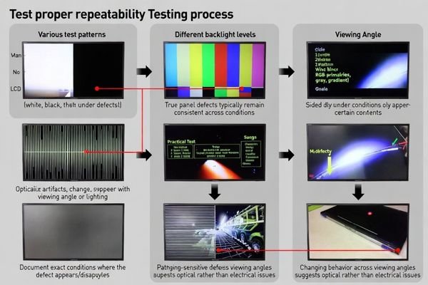
Repeatability3 is your strongest evidence. If the line appears only on a narrow set of patterns, document exactly which ones and why they matter (for example, mid-gray and gradients can reveal subtle drive margin issues). If the line is visible on typical UI content at normal viewing distance and angle, it is much more likely to be field-relevant and should be treated more strictly.
Does the defect align with pixel rows/columns or the mechanical stack?
Alignment analysis provides critical diagnostic information distinguishing electrical panel defects from mechanical stress and optical stack issues through systematic position mapping.
Alignment is a strong clue. Lines that are perfectly straight and track exact pixel rows/columns often point to row/column drive, TAB/COF bonding, or internal panel faults—especially if the width matches a pixel or a small fixed number of pixels. Lines that curve, change with pressure, shift with mounting torque, or cluster near bezels can indicate mechanical stress, uneven support, or optical stack interactions.
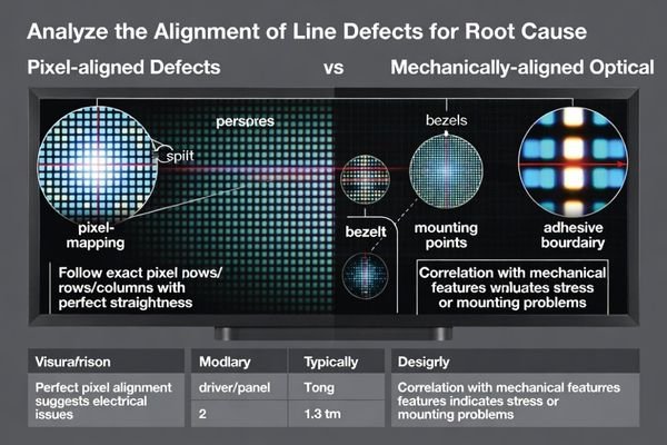
Map the line location against both the pixel grid and mechanical features (bezel edges, screw points, adhesive boundaries, gasket interfaces). If the artifact moves or changes with enclosure condition, treat it as an integration-sensitive symptom until proven otherwise. If it is pixel-locked and invariant to mechanical changes, the evidence favors a module-level abnormality.
| Alignment Characteristic | Typical Root Cause | Diagnostic Indicators |
|---|---|---|
| Perfect Row/Column Tracking4 | Driver IC or bonding issue | Pixel-width precision, electrical boundary alignment |
| Mechanical Feature Correlation | Assembly stress or mounting | Proximity to screws, bezels, or adhesive edges |
| Curved or Variable Width | Optical stack interaction | Pressure sensitivity, angle-dependent visibility |
| Edge-Adjacent Positioning | Optical stack surface/contamination effects | Consistent distance from bezel, changes with lighting/angle |
Use the table as a documentation template: record the observed alignment characteristic and the supporting indicators, then attach photos/video under the defined test conditions so the supplier can reproduce the same view.
What quick electrical and interface checks rule out "false line defects"?
Systematic elimination of host-side and signal-chain causes prevents misclassification of integration-induced artifacts as panel abnormalities through controlled validation testing.
Before declaring abnormality, rule out host-side causes: verify stable power rails and backlight conditions, confirm interface integrity (connector seating, FPC strain relief, grounding), and ensure initialization and timing remain correct after resets. Marginal signal integrity or timing can create line-like artifacts under specific patterns or temperatures. If the line disappears on a known-good reference driver/fixture, suspect integration rather than a module defect.
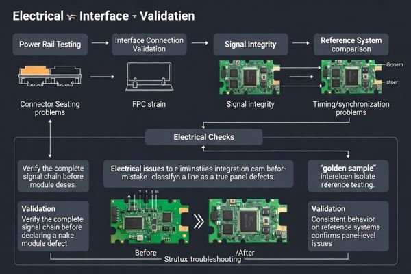
These checks should be quick and objective: confirm connector engagement, remove cable strain, compare behavior across resets, and repeat tests under stable conditions. If you can reproduce the symptom only when the system is in a particular state (after warm-up, after a mode change, at certain refresh settings), that strongly suggests a timing/margin issue rather than a damaged panel.
Power and Backlight Validation
Verify that key rails are stable and within expected limits during the defect observation, and that backlight settings are consistent between “good” and “bad” cases. Power droop, ripple, or unstable backlight drive can exaggerate artifacts or create borderline behavior that looks like a line defect.
Interface and Signal Integrity Testing5
Confirm that the interface is not introducing data errors: check cabling, connector seating, and any conditions that reduce margin (long cables, poor grounding, mechanical strain). If available, reproduce on a reference system with controlled power and known-good timing; this is one of the fastest ways to separate module abnormalities from integration issues.
How do you define an "abnormal" line defect for incoming inspection and acceptance?
Objective abnormality criteria require measurable inspection conditions, clear defect characteristics, and application-specific acceptance thresholds enabling consistent quality decisions and supplier alignment.
Make “abnormal” enforceable by defining inspection conditions and pass/fail rules, not subjective terms. Specify patterns, brightness setting, viewing distance/angle, and ambient lighting; then define rejection triggers by type (bright/dark/color), orientation, location (active area vs edge), continuity (full-length vs segment), and visibility (only on gray vs visible on normal UI). Include repeatability and permanence rules, and set thresholds based on application risk.
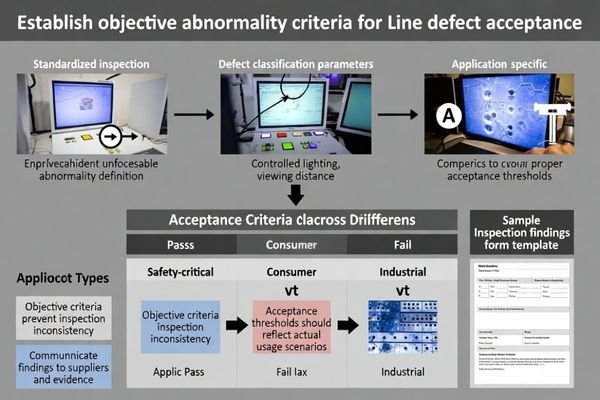
Acceptance criteria should reflect real use. For customer-facing or safety-relevant HMIs, a line visible under normal operating content is typically unacceptable. For internal/debug displays, criteria may be looser—but the rule still needs to be explicit so inspectors and suppliers judge the same way.
Inspection Condition Standardization
Controlled Testing Environment:
- Test patterns: Solid white, solid black, 50% gray, representative UI content
- Backlight setting: Nominal brightness level specified for application
- Viewing conditions: Normal viewing distance (arm’s length), perpendicular viewing angle
- Ambient lighting: Controlled office lighting (300-500 lux) or application-representative conditions
Documentation Requirements:
- Digital photo/video under the defined pattern and viewing setup
- Recorded conditions (temperature, backlight setting, viewing angle/lighting)
- Reproducibility steps (how to trigger, how long to warm up, what state)
- Standardized reporting format for supplier feedback
Defect Classification and Acceptance Criteria
- Continuous lines spanning >50% of active area height/width
- Lines visible on normal UI content under standard viewing conditions
- Lines affecting critical display areas specified for application requirements
- Multiple line defects indicating systematic panel or drive issues
Conditional Acceptance:
- Partial lines limited to non-critical edge areas (as defined by the product)
- Lines visible only on diagnostic solid patterns but not on representative UI
- Temperature-dependent lines that do not appear within the specified operating window
- Lines below the agreed visibility threshold under the defined inspection setup
Application-Specific Thresholds:
- Safety-critical displays: Zero tolerance for lines visible under the defined inspection conditions
- Industrial HMI: Threshold based on operational area impact and readability requirements
- Consumer displays: Criteria aligned to user experience expectations and product positioning
- Debug/development displays: Criteria focused on functional impact rather than cosmetics
FAQ
How can I tell if a line is a panel defect or a reflection/optical artifact?
Check whether it stays in the same pixel location across solid colors and persists across normal viewing angles. Artifacts often change with angle or lighting, while true panel defects remain fixed.
If a line appears only on gray backgrounds, is it still abnormal?
It can be. Gray patterns reveal small drive or uniformity issues; if it is repeatable and visible under realistic UI conditions, it should be treated as an abnormality for many applications.
Why does a line defect change after warm-up?
Temperature can shift drive margins and optical behavior. Marginal electrical contacts or stress-related effects may become visible only after thermal expansion or stabilization.
Can interface timing issues create line-like artifacts?
Yes. Marginal signal integrity or timing can create consistent-looking line errors, especially under specific patterns or high refresh/throughput conditions.
What is the fastest way to verify whether it’s an integration issue?
Re-test the module on a known-good reference driver/fixture with controlled power and backlight. If the line disappears, focus on host timing, cabling, and mechanical mounting.
How should I document a line defect for supplier feedback?
Record photos/video with the test pattern and conditions, note temperature/backlight setting, describe location/length/width, and include repeatability steps so the supplier can reproduce it.
Conclusion
Determining whether a line defect is abnormal comes down to evidence: controlled repeatability, fixed alignment to the pixel grid, and elimination of host-side and optical artifacts. By testing across patterns and viewing conditions, mapping the line to pixel and mechanical features, and validating on a reference setup, teams can separate genuine module defects from integration-induced symptoms and make consistent acceptance decisions.
LCD Module Pro supports LCD display module quality evaluation with practical inspection criteria development, repeatable test-condition definitions, and structured supplier feedback packages to reduce disputes, rework, and unnecessary returns.
✉️ info@lcdmodulepro.com
🌐 https://lcdmodulepro.com/
-
Understanding evidence-based workflows can enhance your decision-making process, ensuring reliability and accuracy in various fields. ↩
-
Understanding line defects is crucial for effective troubleshooting and quality control in display technology. ↩
-
Understanding repeatability can enhance your evidence collection methods, ensuring reliability and accuracy in your findings. ↩
-
Exploring this topic can provide insights into display performance and troubleshooting techniques. ↩
-
Learning effective methods for interface and signal integrity testing can prevent data errors and improve system performance. ↩
-
Exploring common rejection triggers can help you identify critical defects early, ensuring higher quality standards in your products. ↩