Validate MIPI DSI compatibility by freezing link settings, stressing bring-up across corners, and verifying initialization and state transitions are repeatable with real interconnects and power conditions.
MIPI DSI compatibility is a host-to-module contract, not a connector match. Prove PHY margin, protocol/mode behavior, and repeatable reset/power/init flows. A module may “work once” yet fail across temperature, ramps, or FPC variation—so compatibility must be demonstrated across the full operating envelope with clear pass/fail evidence.
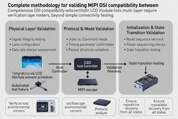
Many bench-pass builds fail later due to configuration drift1, narrow timing windows, or interconnect differences. A production-ready plan produces repeatable evidence: frozen settings, defined cycle counts, corner coverage, and clear failure signatures for diagnosis and regression.
What does "MIPI DSI compatibility" really mean for an LCD module?
MIPI DSI compatibility encompasses comprehensive interface contract including physical layer parameters, protocol behavior, and system-level integration requirements beyond simple connector and signal matching.
For an LCD module, compatibility means the host repeatedly links, initializes, and displays correctly—without “lucky boots.” It must pass cold boot, fast power cycles, and sleep/wake across temperature, supply tolerance, and realistic FPC/cable variation, with predictable recovery from disturbances.
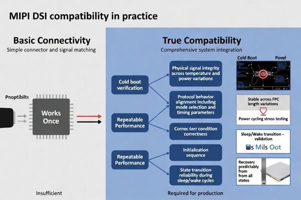
Compatibility is best defined as repeatable behavior under controlled, documented conditions. If stability depends on extra resets, a specific ramp profile, or one short lab FPC, the system is not yet compatible for production. Your validation target should be:
(1) stable physical link margin,
(2) correct protocol and mode behavior for your content and timing, and
(3) consistent initialization and state transitions that recover cleanly after sleep/wake and fast cycling. Treat “works once” as a warning sign and require repeatable pass rates across corner conditions.
Physical Layer Compatibility Requirements2
Physical layer compatibility encompasses electrical signaling parameters, lane configuration, data rate margins, and termination characteristics that must align between host controller and LCD module to ensure reliable signal transmission and reception under varying operating conditions and manufacturing tolerances.
The physical layer is compatible when the chosen lane count and data rate provide enough margin across temperature, supply tolerance, and interconnect variation. In practice, that means the link locks quickly and stays locked when the FPC length changes within the approved range, when the system warms up, and when the power rails ramp at the slowest and fastest expected edges. If the image shows intermittent blanking, a lane drop, or frame corruption during transitions, treat it as a PHY margin signal until proven otherwise.
Protocol and Behavioral Layer Integration
Beyond electrical compatibility, successful DSI integration requires protocol layer alignment including operating mode selection, packet formatting, timing requirements, and behavioral compatibility covering initialization sequences, power state transitions, and error recovery mechanisms that affect system-level reliability and user experience.
Protocol/behavior compatibility means the module receives the right mode and timing assumptions and responds predictably to state changes. Confirm whether the system uses video or command mode, whether TE is required, and whether porch/blanking behavior matches the module’s expectations. Then validate behavior: reset timing, power sequencing, initialization commands, and sleep/wake flows must not leave the module stuck, slow to recover, or gradually unstable. A module that “looks fine” but fails during resume or fast cycling is not behavior-compatible.
Which interface parameters must be matched and frozen before testing?
Systematic parameter documentation and configuration control prevents validation inconsistencies and ensures test results accurately reflect true compatibility performance.
Freeze the DSI baseline before testing: lane count/mapping, target data rate and margin strategy, clocking mode, burst/non-burst behavior, and video vs command mode. Lock pixel format, resolution, porch/blanking, TE usage (if applicable), and reset/power sequencing. Also lock FPC/cable length targets, impedance assumptions, grounding, and EMI/ESD constraints—because changes here can dominate stability.
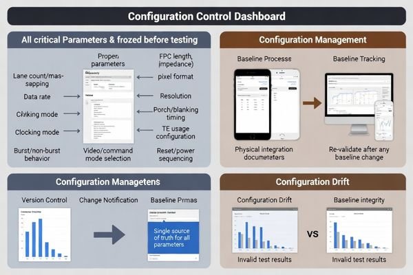
A frozen baseline prevents “configuration drift” from being misread as incompatibility. Create a single source of truth3 that includes the host DSI settings, the timing parameters (including porches/blanking and frame rate targets), and the physical integration assumptions (approved FPC types and lengths, connector, grounding, and shielding approach). Confirm the host platform can actually execute the plan: independent rail control if sequencing matters, a reset line under software control, and logging that records boot/resume outcomes and failure signatures. If any baseline item changes—lane rate, porches, mode, TE usage, or the interconnect—you should treat the change as a compatibility event and re-run the critical subset of tests.
How do you validate link bring-up stability and signal margin on MIPI DSI?
Link stability validation requires systematic stress testing across operating conditions, timing variations, and physical interconnect scenarios to ensure reliable DSI communication.
Prove bring-up margin with repeatable stress. Confirm reset release, lane enable, and clock transitions occur in the correct order and within the module’s timing window. Stress corners using realistic interconnects, temperature extremes, supply tolerance, and product-relevant EMI/ESD. Define pass/fail by cycle count and recovery behavior, and record failure signatures while varying data rate/lane count to understand margin.
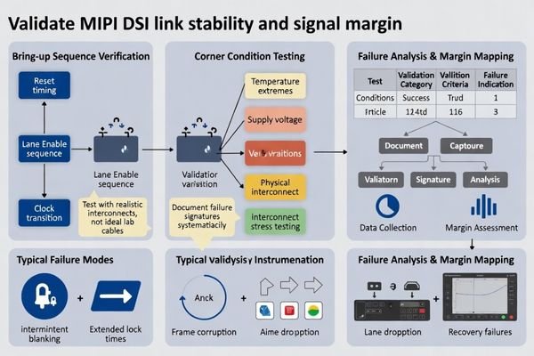
| Validation Category | Test Conditions | Success Criteria | Failure Indicators |
|---|---|---|---|
| Bring-up Sequencing | Multiple reset cycles, timing variations | Consistent lock within specification | Intermittent blanking, extended lock times |
| Environmental Stress4 | Temperature extremes, supply tolerance | Stable operation across corners | Frame corruption, lane dropping |
| Interconnect Robustness | FPC length variants, impedance changes | Signal integrity maintenance | Data errors, link instability |
| EMI/ESD Resilience | Interference exposure, electrostatic stress | Continuous operation without disruption | Reset behavior, communication failure |
| Power Cycling Stress | Cold boot, fast cycles, sleep/wake loops | Reliable transitions without manual intervention | Stuck states, recovery failures |
After the table, document results with consistent evidence: the same test pattern, the same corner matrix, and the same cycle counts. If a failure appears, log what the system was doing (boot, resume, rate change, temperature step) and what the display showed (blanking, flicker, corruption, lane drop). Then change one variable at a time—rate, lane count, timing window, or interconnect—to see what restores stability. This converts “random” failures into margin data and prevents fixes that only shift the test setup.
How do you verify the initialization sequence and command set correctness?
Initialization verification confirms command sequence accuracy, timing compliance, and behavioral repeatability ensuring reliable module startup and state transition behavior.
Validate initialization as a controlled contract. Confirm the reset/power-up sequence, required delays, and the complete init script from reset to stable display. Verify required behaviors—display on/off, sleep in/out, wake timing, TE usage (if applicable), and update behavior for your UI. Prove repeatability through cycling and treat the init script as a version-controlled item.
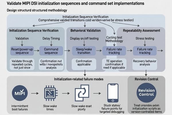
Initialization failures often present as intermittent boot, slow wake, or rare stuck states that only appear under specific timing and power conditions. To avoid “works once” conclusions, define the exact sequences you will test (cold boot, fast cycle, sleep/resume loops), capture logs on every failure, and confirm that recovery does not require manual resets. Keep the init script aligned to the frozen baseline so timing, porches, and mode assumptions don’t drift during troubleshooting.
Command Sequence Verification and Timing Analysis
Validate that the init script matches the module’s required order, delays, and mode selection, and that the panel reaches a stable state consistently. Test the behaviors your product depends on—display on/off, sleep in/out, wake time, TE usage if applicable, and expected update timing—then repeat those transitions many times to catch narrow timing windows. When issues occur, record the exact point of failure and the visible symptom so fixes can be verified objectively.
Repeatability Assessment and Revision Control
Prove repeatability by running extended boot and resume cycling, not just a few manual trials. Track wake time and failure rate so marginal conditions are visible before production. Treat the init script5 and critical timing assumptions as configuration-controlled artifacts: require change notification, keep golden references, and re-validate the critical scenarios whenever the module revision, controller behavior, or baseline timing parameters change.
How to choose an LCD module solution that reduces MIPI DSI compatibility risk?
DSI compatibility risk reduction requires systematic selection methodology considering host capabilities, module requirements, integration constraints, and lifecycle management factors.
Reducing DSI compatibility risk starts with aligning host capabilities with module requirements while planning for robust integration and long-term lifecycle management.
Host/Module Fit and Margin Planning
Choose a module whose lane count and data rate fit your platform without running at peak throughput, leaving margin for temperature corners and interconnect variation. Ensure the selected operating mode (video or command) matches your UI behavior and update needs, and confirm your host can meet the required timing windows, porches/blanking, and reset/power sequencing with repeatable control. If you must reduce data rate for margin, treat it as a planned trade-off that still meets frame rate and visual requirements.
Integration and Lifecycle Controls
Design the interconnect and grounding strategy for signal integrity6 at the chosen rate, and validate using realistic FPC lengths and assembly tolerances rather than a single ideal lab cable. Lock the baseline configuration and the init script, keep golden references, and require revision transparency from the supplier. Define a re-validation checklist for module revisions or alternates that covers cold boot, fast cycling, sleep/wake, and corner temperatures, so a “same interface” replacement does not introduce hidden bring-up or resume differences.
FAQ
If the host supports MIPI DSI, will any DSI module work?
Not necessarily. Compatibility depends on lane/rate margin, mode (video/command), initialization commands, and power/reset timing, not just the protocol name.
Why does a module work at room temperature but fail in cold or hot conditions?
Temperature changes can shift signal margin, timing windows, and panel behavior, exposing marginal link or sequencing that was “just enough” at room temperature.
Is lowering the data rate a valid way to improve compatibility?
Often yes, as it increases signal margin, but it must still meet frame rate and UI requirements; it should be treated as a design trade-off, not a last-minute patch.
Do we need to validate both cold boot and sleep/wake for DSI modules?
Yes. Many failures only appear during resume or fast power cycling, so both scenarios should be part of the compatibility checklist.
What causes "intermittent flicker" or occasional frame corruption on DSI?
It can be marginal signal integrity, unstable bring-up timing, EMI coupling, or a mismatch in mode/timing assumptions; stress testing across corners helps identify which factor dominates.
How do we manage compatibility when the module revision changes?
Treat initialization scripts and critical timing as controlled artifacts, require change notification, keep golden samples, and re-validate cold boot, resume, and corner cases after changes.
Conclusion
Validate MIPI DSI compatibility by proving PHY margin, mode/protocol behavior, and repeatable init/state transitions across real corners. Freeze the baseline, stress bring-up and recovery, and control scripts and revisions so results remain valid in production.
LCD Module Pro supports MIPI DSI validation for LCD modules with baseline definition, corner-stress test planning, init-script control, and re-validation checklists for revision or supplier changes.
✉️ info@lcdmodulepro.com
🌐 https://lcdmodulepro.com/
-
Understanding configuration drift is crucial for maintaining system stability. Explore this link to learn effective management strategies. ↩
-
Understanding these requirements is crucial for ensuring reliable signal transmission and system stability. ↩
-
Exploring the concept of a single source of truth can enhance your data management strategies and improve decision-making. ↩
-
Understanding Environmental Stress can help you ensure stable operation of your devices under extreme conditions. ↩
-
Understanding the init script’s role is crucial for ensuring proper module functionality and stability. ↩
-
Exploring signal integrity techniques can help you design robust interconnects that minimize errors and improve performance. ↩