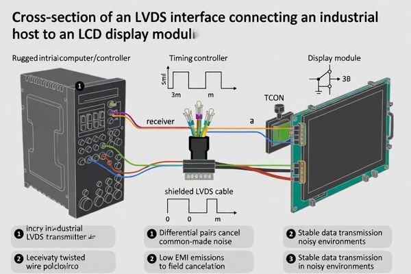
LVDS is a differential signaling standard used in LCD display modules to transport high-speed pixel data from an industrial host with strong noise immunity—one of the reasons it’s still a go-to interface in demanding industrial environments.
In plain terms, LVDS pushes pixel data over paired, high-speed differential lines, which helps it survive noisy enclosures. In an LCD display module, the host outputs serialized video data into the module’s timing controller (TCON), which then drives the panel. I still call it a “video highway” for industrial gear—stable, predictable, and EMC-friendly—when pinout, mapping, timing, and cabling are truly matched.
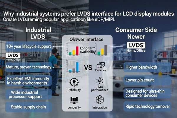
In my LCD display module integration work at LCD Module Pro, LVDS remains one of the most requested interfaces for industrial projects. While newer standards like eDP and MIPI dominate consumer devices, industrial teams usually care more about stability, predictable integration, and long-term availability than having the newest display pipeline features.
That said, LVDS1 can fool people because it feels like it should be plug-and-play. It isn’t. Most project delays I see happen when a team assumes “LVDS is LVDS,” then discovers late that the host output and module input don’t align—mapping, bit depth, timing, connector pinout, or the realities of the cable inside a noisy metal box. If you get those details right, LVDS is extremely reliable.
What exactly is LVDS in an LCD display module?
In an LCD module, LVDS is a high-speed digital interface that transmits serialized pixel data over twisted-pair copper wires, providing a noise-resistant connection between the host system and the display’s timing controller (TCON).
LVDS is basically a way to move display pixel data as high-speed differential signals so it can travel through a cable with better noise immunity than single-ended signals. In an LCD display module context, LVDS usually means the host board sends serialized video data (plus clocks/control) into the module’s timing/controller side, and the module turns that stream into the panel’s drive signals. It’s common in industrial designs because it stays stable in noisy enclosures—assuming mapping, timing, and pinout really match.
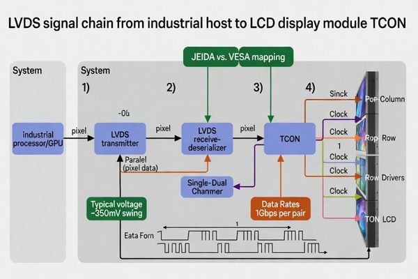
From an engineering standpoint, the core benefit of LVDS (Low-Voltage Differential Signaling) is its use of differential pairs. Instead of sending a signal on a single wire relative to ground, it sends two signals with opposite polarity on a pair of wires. The receiver looks at the difference between these two signals. In practice, LVDS for LCD modules is often used in FPD-Link style links over twisted pairs, where the cable and return path are part of the interface, not an afterthought.
Why Differential Signaling Matters
This approach provides two major advantages for an industrial environment:
- Common-Mode Noise Rejection: Electrical noise from motors, power supplies, or radio frequencies tends to affect both wires in a pair equally. Since the LVDS receiver only cares about the difference between the two signals, this "common-mode" noise is effectively canceled out. This is why LVDS is so robust in noisy factory settings or vehicles.
- Reduced EMI Emissions2: Because the two signals in a pair are equal and opposite, the electromagnetic fields they generate largely cancel each other out. This results in much lower radiated emissions (EMI) compared to single-ended interfaces like parallel RGB, making it easier for the final product to pass EMC certification.
The Role of the TCON
When the serialized LVDS data arrives at the LCD module, it is received and de-serialized by the Timing Controller (TCON). The TCON then converts this data stream back into the parallel signals needed to drive the panel’s gate and source drivers, which control the individual pixels. Essentially, the LVDS interface is the high-speed link that feeds the TCON the information it needs to create the image.
Why do industrial systems still choose LVDS?
Industrial systems continue to choose LVDS for its proven reliability, long-term availability, and predictable integration, prioritizing stability over the latest consumer-grade interface features.
LVDS is “boring” in the best industrial way: it’s mature, widely supported, and behaves well in noisy metal enclosures. Many industrial UIs don’t need cutting-edge features—they need predictable pixels for years. Teams choose LVDS to buy integration stability and supply continuity, not to chase interface trends.
When I troubleshoot field issues, it’s rarely a well-implemented LVDS system causing the problem. Its predictability is its biggest strength. Industrial customers are not building products that will be replaced in two years; they’re building equipment that needs to operate reliably for a decade or more.
This long-term perspective makes LVDS attractive for several reasons:
- Maturity and Stability3: The technology is well-understood. The design rules for PCB layout, cable construction, and grounding are established best practices, reducing integration risk.
- Broad Silicon Support: A wide range of industrial-grade processors, SoCs, and FPGAs have native LVDS outputs. This simplifies the host board design and can avoid the need for interface bridge chips.
- Supply Chain Longevity: LVDS has been a cornerstone of the industrial market for a long time, with a stable supply chain for LVDS-enabled displays and supporting components, helping reduce premature End-of-Life (EOL) risk.
- Practical Performance: For most industrial user interfaces—process data, controls, dashboards—single or dual-channel LVDS bandwidth is often sufficient without needing newer interface complexity.
Choosing LVDS is often a strategic decision: prioritize uptime and supply security over peak interface performance.
Which industrial hosts does LVDS fit best?
LVDS is an ideal fit for industrial hosts with native LVDS outputs, such as industrial PCs, embedded single-board computers, and custom mainboards designed for HMIs, kiosks, and transportation systems.
LVDS fits best when the host exposes LVDS natively—industrial PCs, fanless box PCs, panel PC mainboards, and embedded compute boards used for HMIs, test equipment, automation controllers, kiosks, and vehicle/rail subsystems. The closer you stay to native LVDS, the fewer variables you introduce. “Has LVDS” is only step one—channel count, bit depth, mapping, timing, backlight control, and connector conventions must still align.
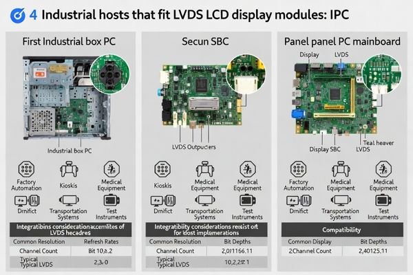
Based on the projects I support with OEMs and system integrators, the smoothest integrations happen when the display choice follows the host’s native capabilities. Using an LVDS display module with an LVDS-native host removes a whole category of potential failure points.
| Host Type | Typical Application | Why LVDS is a Good Fit |
|---|---|---|
| Industrial PC (Box/Panel PC) | Factory Automation, Process Control | LVDS headers are common on many industrial mainboards, and LVDS noise immunity4 suits factory EMI environments. |
| Single-Board Computer (SBC) | HMI, Kiosks, Embedded Systems | Many industrial SBCs offer LVDS outputs for direct panel connection, simplifying packaging and integration. |
| Vehicle/Rail Computers | In-Cab Displays, Passenger Information | Noise immunity and tolerance for complex wiring make LVDS a strong fit in transportation systems. |
| Test & Measurement Equipment | Instrument Displays, Control Panels | A reliable, low-noise display link is valuable when showing critical data and controls. |
The key takeaway: “LVDS present” is not the same as “LVDS matched.” The host datasheet must be cross-checked with the display module datasheet for channel count (single/dual), bit depth (commonly 6-bit/8-bit), and mapping formats (often JEIDA vs. VESA). If there’s a mismatch, you may need an adapter board or custom interconnect, which adds risk. If your host has a non-standard LVDS implementation, discussing a custom module or matching interconnect with an engineering-focused supplier like LCD Module Pro can be a cleaner way to avoid stacking adapters. For a technical consultation, you can reach our team at info@lcdmodulepro.com.
What are the most common LVDS integration pitfalls?
The most common pitfalls are timing/mapping mismatches causing visual artifacts, and poor cable/grounding design leading to EMI failures or intermittent signal loss in the final product enclosure.
If the screen powers up but looks wrong, check mapping and timing first. If it works on the bench but fails in the enclosure, suspect cable routing, shielding, connectors, and grounding. LVDS isn’t plug-and-play—the cable and return path are part of the interface, and enclosure validation is where the truth shows up.
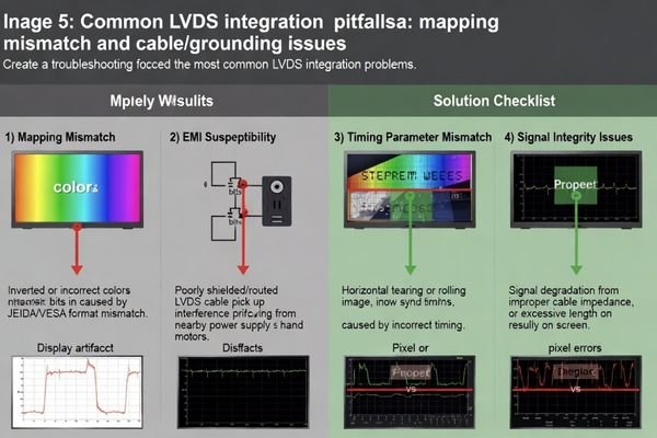
In my experience, almost all LVDS integration problems fall into one of these categories, and they’re avoidable with careful upfront engineering.
-
Data Mapping and Bit Depth Mismatch:
This is the classic "it turns on but the colors are wrong" problem. If the host is sending data in the JEIDA format but the display expects VESA format, pixels will be mapped incorrectly. Similarly, connecting an 8-bit host to a 6-bit panel without proper configuration can result in missing color shades or visual banding. Solution: Verify mapping and bit depth in both datasheets before ordering hardware. -
Incorrect Timing Parameters5:
If the host’s pixel clock frequency, or the horizontal/vertical timing parameters (porches, sync pulse widths), are outside the range the TCON expects, you can get a rolling screen, shimmering, or no image at all. Solution: Ensure the host’s display driver configuration matches the "Typical Timing" specifications in the module datasheet. -
Poor Cable and Connector Quality:
On the bench, a simple ribbon cable might work. But inside a metal box next to a switching power supply, that cable can act as an antenna. Using a cable without proper impedance control (e.g., ~100 ohms), inadequate shielding, or poor connector strain relief is asking for trouble. Solution: Use a shielded LVDS cable with controlled impedance, secure connector retention, and routing away from noisy power nodes, then validate in the final enclosure. -
Backlight Power and Control Issues:
The backlight is often a separate electrical system. Driving it with a noisy PWM signal can induce flicker or even audible whining. Insufficient power can cause the display to trip undervoltage protection and reset. Solution: Validate the backlight driver with the final power supply and PWM source, testing across the full dimming range and realistic power events.
How I match an LVDS LCD display module to an industrial host
My process prioritizes risk reduction by starting with the host’s capabilities, locking down the end-to-end signal chain, and validating performance within the final system context, not just on a lab bench.
I start from the host, not the panel. Lock single/dual channel, pixel clock, mapping (JEIDA/VESA), and bit depth first—then treat the cable, connector, and grounding as part of the interface. If you validate inside the real enclosure early, you prevent the late-stage “almost works” debugging trap.
When a client asks for help selecting an LVDS module, I follow a practical process designed to prevent the common pitfalls I’ve seen derail schedules.
-
Host Capability First: Before looking at displays, I get the host datasheet and confirm LVDS output details: channel count, supported pixel clock, bit depth, and mapping formats. This sets the hard constraints and prevents guessing later.
-
Find a Matching Module: With the host profile in hand, I look for display modules whose LVDS input requirements match directly, so we can avoid adapter boards and reduce variables.
-
Define the Interconnect Strategy: I treat the connector + cable + pinout as a single critical component. We specify connector part numbers, cable type (shielded, twisted-pair, controlled impedance), pinout, retention, routing, and the length margin we can realistically support—then we validate it in the enclosure.
-
Verify Power and Control: I map power for panel logic and backlight, confirm supply headroom, and document backlight control (PWM/analog, levels, enable behavior). Then I test across the full dimming range and realistic power events.
-
Mechanical and Thermal Fit: Once electrical is solid, I confirm mounting, connector clearance, strain relief, and whether there’s an adequate thermal path for the backlight and TCON in the real chassis.
-
Lifecycle and Supply Chain Review: Finally, I check production status, supplier lifecycle policy, and practical migration options. Industrial products last a long time, so continuity planning matters as much as first-article success.
FAQ
Is LVDS the same as eDP?
No. They are different interfaces with different electrical and protocol layers. If your host is eDP-only, you shouldn’t assume it can drive an LVDS module without a proper bridge chip and thorough validation.
What does “single-channel vs dual-channel LVDS” mean in practice?
It mainly sets bandwidth. Practical limits depend on pixel clock, bit depth, blanking, and mapping. You must match the host’s LVDS capability to the module’s requirement, then validate margins in your system.
Why do colors sometimes look wrong on an LVDS display?
The most common causes are an incorrect data mapping setting (often JEIDA vs. VESA) or a bit-depth mismatch between the host and the display module. It often "almost works," which is why it’s frustrating if not checked upfront.
How long can an LVDS cable be?
There isn’t a universal safe length. It depends on pixel clock, cable quality, shielding, routing, and the EMI environment. Shorter is easier, and any length should be validated in the final enclosure. I often see sub-meter runs work well with good shielding at moderate clocks, but you should verify in your design.
What’s the best way to reduce LVDS EMI issues?
Start with controlled impedance, tight pair coupling, and a properly shielded cable. Route away from high dv/dt power nodes, and make grounding/return paths intentional. Then verify under worst-case system switching conditions.
When should I choose a custom module instead of adapting a standard one?
If your host has a non-standard connector, unusual mapping, strict EMC constraints, or tight mechanical limits, a custom module/interconnect approach is often cleaner than stacking adapters and hoping it stays stable in production.
Conclusion
LVDS remains popular in industrial LCD display modules because it’s mature, noise-resistant, and predictable—when the implementation is disciplined. The real win is treating LVDS as an end-to-end signal chain: host output details, mapping/timing, connector/pinout, cable/shielding, and grounding, all validated in the real enclosure.
If you want to de-risk an LVDS integration, LCD Module Pro can help review host outputs, mapping/timing assumptions, and the interconnect strategy so you avoid late-stage surprises. For a technical consultation, contact us.
✉️ info@lcdmodulepro.com
🌐 https://lcdmodulepro.com/
-
Understanding LVDS is crucial for successful integration in industrial projects, ensuring stability and compatibility. ↩
-
Exploring Reduced EMI Emissions will provide insights into improving device performance and compliance with EMC standards. ↩
-
Understanding the maturity and stability of LVDS technology can help you make informed decisions about its reliability and integration. ↩
-
Learn about noise immunity’s role in display technology to ensure reliable performance in challenging environments. ↩
-
Exploring this topic can help you avoid common display issues like rolling screens and ensure optimal performance. ↩