If you’ve worked with embedded displays, you’ve probably noticed that “DSI” shows up again and again—especially on ARM boards. The reason isn’t hype; it’s that DSI fits the practical constraints of compact products and integrated SoC display pipelines.
MIPI DSI is a high-speed serial interface that carries pixel data and control commands over a few differential lanes from an ARM host SoC to an LCD display module. It’s not just a connector: real compatibility depends on lane count and rate, video vs command mode behavior, clocking, and a correct initialization sequence. That “contract” is why modules may not be drop-in interchangeable.
In my LCD display module integration work at LCD Module Pro, I see DSI projects most often when a customer’s host platform is an ARM SoC with a built-in DSI block. That choice is usually made upstream—by the SoC vendor and the board design—not by the display team. So the real question becomes: how do we make that DSI link1 stable across production hardware, real cables, real EMI, and real boot/resume behavior?
The easiest way to think about DSI is: it’s flexible, but that flexibility has a cost. You don’t just “connect DSI”; you align configuration, timing, and initialization behavior so the host and module behave like they were designed for each other.
What is MIPI DSI in an LCD display module, in plain engineering terms?
Before we get into why ARM platforms love it, it helps to set expectations: DSI is not a simple replacement for older interfaces where matching pinouts solves most problems. It’s closer to a protocol-driven link that needs agreement at multiple layers.
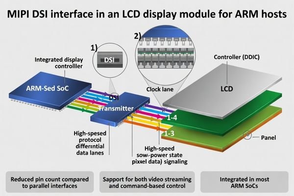
In an LCD display module, MIPI DSI moves pixels and commands over a small number of high-speed differential lanes using a packet-based protocol. The benefit is low pin count and simpler routing versus wide parallel buses. The tradeoff is that you must align link configuration, clocking, and mode behavior, plus the power/reset and init sequence that brings the panel controller into a stable state.
If you strip DSI down to essentials, it’s “high-speed differential lanes + packets + rules.” In typical D-PHY-based designs2, the host and module must agree on how many lanes are used, what rate they run, and how the link behaves during transitions between data streaming and control messaging. That agreement is what prevents the classic “it lights up once, then gets weird” outcome.
High-Speed and Low-Power States
One detail that matters in the real world is that DSI can operate in different signaling states. For high-throughput pixel transport, it uses high-speed differential signaling. For certain control behaviors, it can operate in a lower-speed mode intended to reduce power and simplify some state transitions. You don’t need to memorize the physics—just remember that the link isn’t always in one constant mode, and transitions can expose timing or margin problems if the configuration is tight.
Packet-Based Communication
DSI communicates in packets, not as a raw parallel-like stream. That’s great for pin count and flexibility, but it means the host driver and the module controller must agree on packet formatting, mode behavior, and sequencing. When those assumptions match, integration feels clean. When they don’t, you can see subtle instability—especially during sleep/wake or fast power cycling.
Why is MIPI DSI a good fit for ARM-based platforms?
Most ARM-based systems live in a world where connectors, routing space, and power budgets are limited. That’s exactly where DSI shines—provided you stay within comfortable margins and treat it like a real interface contract.
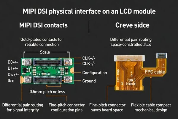
MIPI DSI is common on ARM hosts because many ARM SoCs target compact, power-sensitive embedded designs. DSI delivers high bandwidth with few pins, works well with short FPC interconnects, and integrates cleanly into SoC display pipelines. It can also be easier to route and manage for EMI than wide parallel buses—assuming lane rate, grounding, and cable design are handled with enough margin for real products.
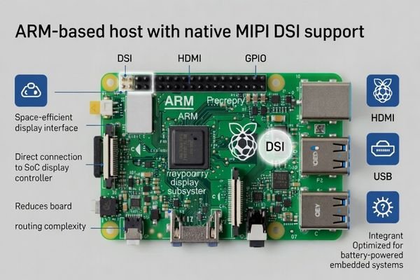
When I support system integrators, DSI is often the “default” simply because the SoC’s display pipeline is designed with native DSI output in mind. Many modern ARM SoCs come with integrated DSI blocks and software support that makes DSI the most straightforward path to a clean embedded display design.
This tight integration brings some practical advantages:
- Reduced Board Complexity: Fewer pins means easier routing, smaller connectors, and fewer layout compromises.
- Power-Friendly Signaling: Differential signaling and flexible behaviors can reduce wasted power compared with older wide buses, especially in UI-centric devices.
- EMI You Can Manage: Differential pairs are typically easier to tame than wide single-ended bundles, though the final result still depends heavily on return paths and grounding.
- Ecosystem Synergy: Many embedded teams already design around MIPI-style high-speed rules3, so DSI fits existing workflows and validation habits.
What are the key DSI mode and timing choices that affect real compatibility?
If you want to avoid painful late-stage surprises, the most important mindset is: freeze the decisions that define the link, and treat them as controlled artifacts. Most “mystery” failures come from margin getting eaten by configuration drift or hidden timing assumptions.
Real DSI compatibility is decided by a few “frozen” choices: lane count and mapping, per-lane data rate with margin, clocking behavior, and video vs command mode. Then come the details that bite later—pixel format, porch/blanking assumptions, TE usage, and exact power/reset timing. If these don’t match the module’s expectations, you’ll see unstable lock, odd artifacts, or failures that only appear during sleep/wake or fast cycling.
When I kick off a new DSI bring-up, I like to lock a small set of parameters early—then never “casually tweak” them without re-testing transitions. These are the ones that most often decide whether you get a stable product or a flaky one:
| Parameter | What it Defines | Common Pitfall |
|---|---|---|
| Lane Configuration4 | The number of data lanes (1, 2, 3, or 4) used to transmit data. | Lane count/mapping differs between the host driver and what the module expects, so link behavior becomes unstable or never fully locks. |
| Data Rate | The speed at which data is transmitted on each lane (e.g., 800 Mbps/lane). | Running too close to limits: it looks fine on a short clean setup, then cable variation, temperature, or EMI pushes it into intermittent failure. |
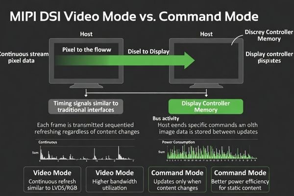
| Operating Mode | Video Mode: Continuous stream of pixel data. Command Mode: Updates sent when needed, depending on module/controller behavior. | Mode assumptions don’t match the controller behavior or driver model, so you get unstable behavior during transitions or certain content states. |
| Initialization Sequence | The specific series of commands and delays required after power-on. | Using a generic init script or missing required delays leads to “sometimes boots, sometimes blank,” especially after fast cycling or resume. |
Getting these four right is what makes integration feel “easy.” If you need help aligning host settings and initialization behavior, our team can support that work—contact us at info@lcdmodulepro.com.
Why do DSI modules sometimes show flicker, blanking, or intermittent bring-up on real hardware?
When a DSI system is borderline, it often behaves nicely in one setup and poorly in another. That’s what makes it frustrating: you can’t trust a single successful boot as proof of compatibility. You need repeatability across transitions and corners.
Most intermittent DSI issues come down to margin and sequencing. If lane rate is too aggressive, small shifts in FPC length, grounding, temperature, or EMI can trigger corruption, brief blanking, or unstable lock. Bring-up also fails when reset release, rail ramp, or init command timing is slightly off, leaving the controller in the wrong state. That’s why validation must include cold boot, sleep/wake, fast cycling, and corner conditions.
When I’m asked to debug a “flaky DSI display5,” I usually follow a basic order: check margin first, then check sequencing, then check mode assumptions. Otherwise you can spend days tweaking init scripts when the real issue is simply that the link is running too close to the edge.
Signal Integrity and Margin Problems
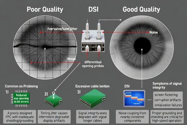
A DSI link can work in a short bench setup and fail in the final product because the interconnect and noise environment changed: longer FPC, different routing, enclosure grounding differences, or proximity to switching power stages. If the lane rate is already aggressive, those changes can reduce eye margin enough to create bit errors. Depending on how the system recovers, you may see pixel corruption, flickering lines, or brief blanking rather than a clean “link down” message.
Sequencing and State Machine Errors
The module controller expects a specific sequence: rails stable, reset timing correct, then init commands sent with required delays. If you violate that sequence—common during fast power cycling or resume—the controller can end up in an unknown state. This is why I always validate sleep/wake and rapid reboot loops, not just the first cold boot, because transition timing is where hidden assumptions get exposed.
How to choose an LCD module solution when your host uses MIPI DSI?
A good DSI module choice is less about chasing maximum specs and more about lowering integration risk. If you plan for margin and validation up front, you’ll spend less time “hunting ghosts” later.
When your host uses MIPI DSI, I choose modules by working backward from the host’s real limits, then leaving margin on purpose. Align lane count, lane mapping, and a data rate that isn’t on the edge. Confirm the required mode behavior and obtain the exact initialization script with timing. Validate the full cable/FPC and power chain, then stress cold boot and sleep/wake loops. Finally, lock revision control so behavior doesn’t drift in production.
When advising a client on selecting a DSI display, I use a checklist aimed at production stability—not just “it lights up once.”
-
1. Confirm Host Constraints:
Document the host’s supported lane count, stable lane rate range, supported modes, and driver behavior. This becomes the baseline contract. -
2. Select for Margin, Not Maximums:
Choose a configuration that meets resolution and frame rate with headroom. Operating comfortably below limits usually turns “intermittent” into “boring,” and boring is what you want in production. -
3. Treat the Initialization Script as a Deliverable:
Get the exact init sequence and required delays for the module. Keep it controlled like firmware, because tiny changes can change stability. -
4. Validate the Full Signal and Power Chain:
Test with production-intent FPC/cable, mechanical assembly, and real power conditions. Bench-only validation is where false confidence is born. -
5. Stress Test State Transitions:
Validate repeated cold boots, fast power cycles, and lots of sleep/resume loops. Transition behavior is where real products fail. -
6. Plan for Lifecycle Management:
Agree on revision control and re-validation triggers. DSI behavior can change subtly across controller or firmware revisions, and you want to catch it before shipments.
FAQ
Is MIPI DSI just a physical connector choice?
No. The connector is only the physical part. DSI is a complex interface specification that includes lane configuration, clocking, operating modes (Video/Command), and a precise initialization sequence. Matching the connector alone does not guarantee compatibility.
Why do many ARM SoCs support DSI natively?
Many ARM SoCs are designed for the mobile and embedded markets, where low pin count, small board size, and power efficiency are critical. DSI’s design aligns well with these goals, making it a natural choice for integrated display pipelines.
What’s the biggest cause of “works in lab, fails in production” for DSI?
A lack of margin. Pushing the data rate too close to limits, combined with variation in FPC quality, grounding, and EMI in the final product, can turn a stable lab setup into intermittent failures.
Should I validate sleep/wake and fast power cycling for DSI modules?
Absolutely. Many subtle timing and sequencing issues only appear during state transitions. A display that boots perfectly from a cold start may fail to resume correctly from sleep, which is why stress testing is essential.
Does lowering the DSI data rate help stability?
Often, yes. Lowering the data rate increases margin for high-speed signals, making the link more robust. However, the rate must still support your required resolution and frame rate.
How do you manage compatibility when the module revision changes?
Treat the initialization script and timing parameters as version-controlled artifacts. Keep a “golden” reference sample. When a new revision arrives, re-validate bring-up, sleep/wake, and stress scenarios to confirm nothing regressed.
Conclusion
MIPI DSI is a powerful and efficient interface for connecting LCD display modules, especially in ARM-based embedded systems where low pin count and compact routing matter. But DSI is not “just a connector”—it’s a complete behavioral contract that includes lane/rate configuration, mode behavior, initialization scripts, and power/reset timing.
From my perspective at LCD Module Pro, reliable DSI comes from discipline: choose a configuration with margin, lock the contract early, and validate transitions (sleep/wake, fast cycling) in production-intent hardware. If you manage DSI as both a physical link and a controlled behavior set, you can build displays that stay stable through manufacturing variation and across the product lifecycle.
✉️ info@lcdmodulepro.com
🌐 https://lcdmodulepro.com/
-
Understanding the DSI link is crucial for ensuring stable connections in LCD displays, making this resource invaluable for your integration work. ↩
-
Exploring D-PHY-based designs can provide insights into their functionality and advantages in modern technology. ↩
-
Learn about MIPI-style high-speed rules to see how they integrate with DSI for better design workflows and validation. ↩
-
Understanding Lane Configuration is crucial for ensuring stable data transmission and avoiding link instability. ↩
-
Understanding the causes of a flaky DSI display can help you troubleshoot effectively and avoid unnecessary delays. ↩