When random snow appears on an LCD display module, the first engineering priority is to avoid assuming that the module itself has failed. In most real integration cases, random snow is a symptom of corrupted or unstable pixel data somewhere in the display chain, not a content problem and not automatically a panel defect.
Random snow on an LCD module usually indicates data corruption in the signal path. The most effective way to locate the fault point is to isolate the display chain step by step, starting with external causes such as cables, connectors, power, grounding, and source output before moving to timing configuration and panel-side behavior. A disciplined troubleshooting sequence is the key to an accurate diagnosis.
![]()
Based on my LCD display module integration work at LCD Module Pro, random snow is one of the most common symptoms that leads teams to the wrong conclusion. The screen is where the problem becomes visible, but the root cause is often located somewhere else. In many prototype-stage cases, the actual fault is found in the cable path, the source output, power integrity, grounding, or interface timing rather than inside the LCD module.
A reliable diagnosis requires controlled isolation1 rather than assumption-based part replacement. Instead of swapping multiple parts at once, engineers should narrow the fault by changing one variable at a time and observing whether the symptom follows the cable, the board, the source, or the module. That approach turns a chaotic symptom into a traceable engineering problem and helps avoid unnecessary replacement costs.
What Does Random Snow on an LCD Display Module Usually Indicate?
Before locating the fault point, it is important to define what random snow actually means from an electrical and system-level perspective.
Random snow on an LCD screen usually means that the pixel data received by the panel is corrupted, unstable, or being interpreted incorrectly. It is typically a hardware-path symptom related to signal integrity, power quality, grounding, or timing rather than a problem in the displayed content itself.
When I troubleshoot this type of issue in the field, I treat random snow as evidence of instability somewhere in the display transmission path. The panel is usually not generating the problem on its own. It is displaying the result of invalid or unreliable incoming data.
The Nature of the Symptom
Random snow can appear in several forms. It may look like flickering white or colored pixels, sparkling points scattered across the image, unstable blocks of noise, or intermittent flashes that change with temperature, cable movement, power cycling, or system load. A panel that lights up normally can still show random snow2 if the incoming pixel stream is only partially valid or becomes unstable under certain conditions.
This symptom is different from a stuck pixel or dead pixel. Stuck and dead pixels are fixed defects at specific locations. Random snow is dynamic, unstable, and often influenced by system conditions, which is why it usually points to a transmission or integrity problem rather than to a static panel defect.
Signal Integrity vs. Panel Defect
In actual integration work, the random and flickering nature of snow is one of the strongest clues that the issue is external to the LCD module itself. A panel defect is more likely to create repeatable lines, stable image distortion, or fixed abnormal areas. By contrast, snow often indicates that the panel is receiving corrupted data, unstable clocking, or poor electrical reference conditions. That is why engineers should first investigate the interconnect path, power rails, timing, and EMI environment before concluding that the panel has an internal fault.
What Are the Most Common Root Causes Behind Random Snow?
Most random snow problems come from a limited group of recurring causes, and the root issue is often found upstream of the LCD module.
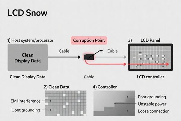
The most common root causes of random snow are unstable power delivery, poor grounding, signal degradation over the cable path, loose or oxidized connectors, incorrect timing parameters, EMI, and host-side output instability. In most prototype-stage cases, the root cause is found outside the LCD module itself.
From an engineering standpoint, I usually start with the highest-probability external causes first because these account for most cases in practical debugging.
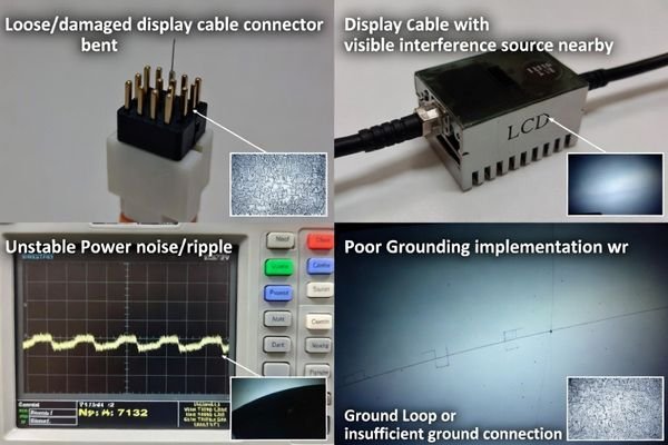
- Power Integrity Issues: An unstable logic voltage rail or excessive ripple can cause the panel-side receiver, timing controller, or related circuits to interpret data incorrectly. This is especially common when logic power and backlight power are not managed cleanly.
- Grounding Problems3: Poor grounding can disturb the reference level of high-speed signals such as LVDS or eDP. In systems with multiple boards or longer cable routes, grounding problems are a frequent source of intermittent snow.
- Cable and Connector Failures: Marginal cable contact, bent pins, oxidized terminals, insufficient retention force, or poor cable quality can all corrupt display data. If the symptom changes when the cable is moved, the interconnect path should be checked first.
- Timing Mismatches: Even when the panel lights up and shows an image, incorrect or marginal timing parameters can still produce unstable pixel data and random snow.
- Electromagnetic Interference: Nearby switching regulators, motors, relays, or wireless modules can inject noise into the display path. Intermittent snow is often consistent with EMI-related interference, especially when the symptom appears only under specific operating conditions.
- Source Output Problems: If the host processor, graphics output, or interface configuration is unstable, the module may simply be showing corrupted input data rather than suffering from an internal display fault.
In actual integration work, cable, grounding, and power issues are more common than internal panel failure. That is why a structured troubleshooting sequence should begin with those external factors.
How Do You Isolate Whether the Fault Comes from the Source, Cable, Power, or Panel?
The fastest way to locate the fault point is to isolate the display chain in a controlled order and change only one variable at a time.
To isolate the fault, start with known-good external references. If the snow disappears after changing the cable or source, the fault is in the original path. If the symptom remains, the next step is to investigate power, grounding, timing, and finally panel-side behavior only after upstream conditions have been verified.
When random snow is reported, I usually guide customers through a sequence that makes the symptom reproducible and then narrows the failure stage systematically.
| Isolation Step | Action to Take | What It Tells You |
|---|---|---|
| 1. Cable Check | Reseat the display cable at both ends, inspect connector pins, gently move the cable, and replace it with a known-good cable. | If movement changes the snow or a new cable eliminates it, the original cable or connector path is the likely fault point. |
| 2. Source Check | Drive the same LCD module and cable from a known-good reference host or signal source. | If the snow disappears, the original source output, software configuration, or interface path is the likely cause. |
| 3. Power Check4 | Measure the logic supply rail and observe whether the symptom changes with power cycling, backlight level, or load conditions. | If snow correlates with power behavior, the problem is likely related to power integrity or grounding. |
| 4. Timing Check | Review timing parameters, initialization sequence, and interface mapping against the module requirements. | If the panel lights up but remains unstable, incorrect timing or mapping may be corrupting the pixel data. |
| 5. Panel-Side Review | Only after the upstream path is validated, review panel-side compatibility or internal reception behavior. | If the issue persists under known-good upstream conditions, panel-side processing or compatibility should be investigated more closely. |
If the issue disappears on a known-good source, the original host path is the likely fault point. If the symptom changes with cable movement, the interconnect path should be checked first. This kind of structured isolation prevents wasted time and avoids replacing a working LCD module when the real problem is somewhere else in the display chain.
Which Diagnostic Methods and Test Tools Help Pinpoint the Fault?
Visual observation is useful, but locating the true fault point requires objective measurements and repeatable test conditions.
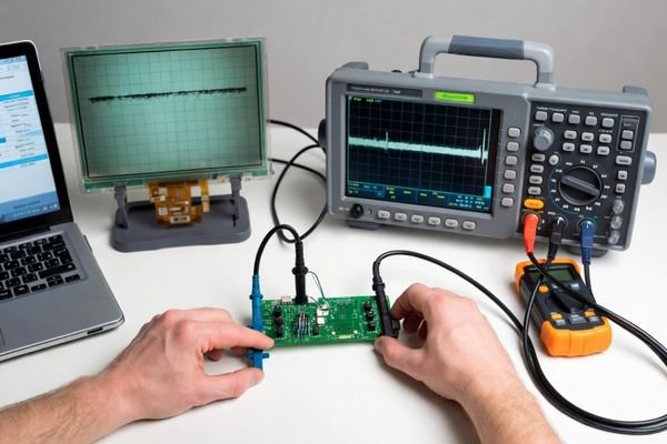
The most effective diagnostic tools for random snow are an oscilloscope, known-good reference hardware, static test patterns, and careful configuration review. These methods help confirm whether the fault is related to power stability, signal quality, interconnect integrity, timing configuration, or EMI.
In practical engineering work, the goal is not just to observe the symptom but to correlate it with a measurable electrical or configuration condition.
The Oscilloscope: A Primary Electrical Tool
An oscilloscope is often the most useful diagnostic tool when random snow appears.
- Power Rail Measurement: Check the LCD module logic supply for ripple, noise, or transient instability. A stable DC reading on a multimeter is not enough if high-frequency noise is present.
- Signal Integrity Review: For LVDS, eDP, or other high-speed interfaces, a suitable oscilloscope can help reveal poor signal quality, excessive jitter, weak eye opening, or noise coupling.
- Correlation Testing: If the symptom changes with backlight load, board temperature, or nearby switching activity, oscilloscope measurements can help confirm whether the underlying cause is electrical instability.
A panel that lights up normally can still receive corrupted pixel data. That is why visual confirmation alone is not sufficient when random snow is involved.
Reference Systems and Test Patterns
Known-good references are essential for narrowing the fault quickly.
- Known-Good Host Source: A stable reference source is one of the fastest ways to determine whether the original host path is causing the problem.
- Known-Good Cable: Replacing the original cable with a verified one helps eliminate a very common fault category.
- Static Test Patterns: A static full-screen color or simple fixed pattern is helpful because any flickering or sparkling noise is clearly unintended and easier to correlate with hardware instability.
- Configuration Review: Timing tables, initialization sequences, lane mapping, and interface settings should all be checked against the display module requirements.
- EMI Investigation5: If the problem appears only when a nearby switching circuit, relay, motor, or wireless source is active, EMI should be considered explicitly.
A strong diagnostic process combines symptom reproduction with electrical verification. Random snow often looks like a panel problem while the real fault is hidden in power, signal quality, grounding, or timing.
What Is the Most Effective Troubleshooting Sequence for Random Snow?
Once the likely fault mechanisms are understood and the right tools are available, troubleshooting should follow a fixed sequence from the most probable external causes to the less common internal causes.
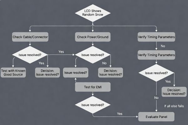
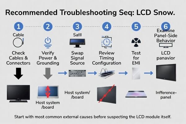
The most effective sequence is to check cables and connectors first, verify power and ground integrity second, isolate the source with a known-good reference third, review timing and interface configuration fourth, and investigate EMI and panel-side behavior only after upstream conditions have been validated.
Based on real debug work, this sequence is the most efficient because it begins with the highest-probability fault categories and avoids unnecessary hardware replacement.
- Check Physical Connections First: Reseat connectors, inspect for bent or oxidized pins, and replace the cable with a known-good reference if possible. This is often the fastest and highest-yield step.
- Validate Power and Grounding6: Measure the logic power rail with an oscilloscope and review grounding quality. If the symptom changes with backlight load or power conditions, focus here.
- Swap the Signal Source: Replace the original host with a known-good source while keeping other variables unchanged. This is one of the most powerful isolation steps.
- Review Timing and Configuration: Confirm timing tables, initialization parameters, interface mapping, and output configuration against the LCD module requirements.
- Investigate EMI and Environment: If the snow is intermittent, correlate it with nearby noisy loads, switching devices, or wireless activity.
- Review Panel-Side Behavior Last: Only after the upstream display path has been validated should the fault investigation move deeper into panel-side reception, compatibility, or internal processing.
This sequence matters because uncontrolled rework can hide an intermittent fault instead of locating it. A disciplined process shortens debug time, reduces misdiagnosis, and improves the long-term reliability of the final design. If you need support reviewing your cable path, interface configuration, or module integration conditions, feel free to contact our engineering team at info@lcdmodulepro.com.
FAQ
Does random snow always mean the LCD display module is defective?
No. In many cases, random snow is caused by signal integrity, power, grounding, timing, or connector issues outside the LCD module itself.
Can a loose cable really cause intermittent snow on the screen?
Yes. Marginal cable contact or connector instability can corrupt display data and create random sparkling pixels or unstable noise.
How do I know whether the problem is related to power or signal quality?
If the symptom changes with backlight load, power cycling, board temperature, or electrical noise sources, power integrity and grounding should be checked carefully alongside signal quality.
Can incorrect timing settings create random snow even if the panel lights up normally?
Yes. A panel may power on and show an image, but marginal or incorrect timing can still cause unstable pixel data and random snow.
What is the fastest way to narrow down the fault point?
A good first step is to replace the source or cable with a known-good reference while keeping other variables unchanged, then observe whether the symptom follows the original path.
Should EMI be considered when snow appears only occasionally?
Yes. Intermittent snow is often consistent with EMI-related interference, especially when nearby switching circuits or noisy loads are active.
Conclusion
When random snow appears on an LCD display module, the fastest way to locate the fault point is to isolate the display chain step by step, starting with cable, connector, power, grounding, and source output before suspecting the LCD module itself. In most real integration cases, random snow is a symptom of signal corruption or electrical instability somewhere in the upstream path rather than proof of an internal panel defect.
At LCD Module Pro, we recommend a disciplined troubleshooting method built on controlled isolation, repeatable testing, and electrical verification. By checking the physical interconnect path, validating power integrity, comparing with a known-good source, reviewing timing parameters, and then considering EMI and panel-side behavior, engineers can locate the true fault point more accurately and avoid unnecessary replacement. A structured approach not only resolves the immediate snow issue but also improves the overall reliability of the LCD module integration.
✉️ info@lcdmodulepro.com
🌐 https://lcdmodulepro.com/
-
Learning about controlled isolation techniques can enhance your troubleshooting skills and reduce unnecessary costs. ↩
-
Understanding the causes of random snow can help you troubleshoot display issues effectively. ↩
-
Exploring Grounding Problems can help you identify and resolve issues that disrupt signal integrity, enhancing system reliability. ↩
-
Exploring power integrity’s role can enhance your troubleshooting skills and ensure reliable display performance. ↩
-
EMI Investigation is vital for identifying interference issues that can affect device performance. ↩
-
This link will guide you through effective methods to ensure stable power and grounding, crucial for troubleshooting electronic issues. ↩