When validating RESET timing and logic level on an LCD display module, engineers should verify both waveform timing and voltage thresholds on real hardware rather than assuming the design is correct from the schematic alone. In practical LCD module integration, RESET is one of the most important startup integrity signals because it determines whether the module’s internal controller begins from a known and stable state.
A display may still power on even when RESET implementation is marginal, which is why this issue is often overlooked during early prototyping. However, intermittent boot failures, unstable images during startup, cold-start problems, or modules that recover only after a second reboot are all classic signs that RESET timing, logic level, or power sequencing may not be fully correct.
Validating the RESET signal on an LCD display module requires oscilloscope-based measurement of pulse width, delay relative to power stabilization, and actual logic levels at the module connector. A proper validation process confirms that RESET timing, voltage thresholds, and startup sequencing all meet the module requirements under repeated real-world operating conditions.
Based on my LCD display module integration work at LCD Module Pro, I have seen many teams spend days investigating what appeared to be a panel fault or software issue, only to find that the real problem was a marginal RESET sequence. For example, if RESET is released before the module’s logic supply and internal controller are fully ready, the startup state may become undefined. The result may be a blank screen, unstable image content, random noise, or a module that works only after several restart attempts.
That is why RESET validation1 should be treated as a core engineering task rather than a quick startup check. A single successful boot is not sufficient evidence of RESET robustness. To achieve reliable initialization in industrial and embedded applications, engineers need to confirm that RESET timing and logic level remain valid across repeated power cycles, different startup conditions, and real hardware measurement points.
Why RESET Timing and Logic Level Matter in LCD Module Integration
The RESET signal acts as the startup control reference for the LCD module’s internal logic. It determines when the controller exits reset and begins normal initialization.
RESET ensures that the LCD module starts from a known, predictable state. If RESET timing or logic level is incorrect, the controller may fail to initialize properly, which can cause blank screens, unstable images, intermittent startup failures, or symptoms that are easily misdiagnosed as panel defects.
In real hardware integration, RESET should always be reviewed together with power sequencing2. A display controller does not respond only to the existence of a RESET pulse. It also depends on when that pulse is asserted, when it is released, and whether the related supply rails and interface conditions are already valid.
The Role of RESET in System Initialization
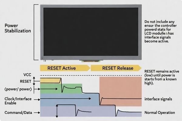
RESET forces the LCD module’s controller and related internal logic into a defined default state during startup. This is important because different parts of the system may become active at different times during power-on. RESET holds the logic in a controlled condition until the supply rails stabilize and the system is ready to begin proper initialization. Only after RESET is released should the controller begin accepting commands, clock activity, or video data.
Common Failure Modes from Marginal RESET
A marginal RESET design can create several difficult startup problems. If the RESET pulse is too short, internal ICs may not complete their reset sequence. If RESET is released too early, the controller may start while the power rail is still unstable or below the required operating threshold. In practice, this can lead to a black screen, flicker, vertical lines, random image artifacts, or a module that fails during cold boot but appears normal after a warm reboot.
What Parameters Should Be Checked During RESET Validation?
A proper RESET validation should confirm more than whether the signal simply toggles. Engineers should review both timing behavior and electrical thresholds against the module requirements.
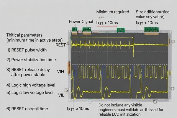
RESET validation should confirm signal polarity, pulse width, delay relative to power stabilization, logic high and logic low levels, and edge quality. Each of these parameters must meet the LCD module or controller requirements to ensure stable initialization.
In most LCD display module projects, the most common RESET integration errors3 come from incomplete validation rather than complete design failure. A circuit may look correct in the schematic, but real startup behavior can still fail because of threshold mismatch, weak pull resistors, GPIO default states, RC delay effects, or incorrect polarity assumptions.
The first parameter to confirm is polarity. The engineer must verify whether the module expects active-low or active-high RESET behavior, because this mistake is more common than many teams expect. Pulse width is the next critical item. The active RESET duration must meet or exceed the minimum specified value in the controller documentation. If it is too short, internal reset completion may not be reliable.
The timing of RESET release relative to the logic power rail is equally important. RESET should not be de-asserted until the relevant supply rail is stable and within the valid operating range. In addition, the logic voltage levels themselves must be checked. The high state must exceed the required V_IH threshold, and the low state must remain below the required V_IL threshold. This matters especially in mixed-voltage systems, where GPIO voltage domains and module input thresholds may not align cleanly.
Engineers should also examine rise time and fall time. A nominally correct signal can still fail if the edge is too slow, distorted, or affected by weak pull-ups or poor level shifting. Logic-level compatibility on the schematic does not guarantee real hardware reliability, so all of these parameters should be verified with actual measurement.
How Do You Measure RESET Timing Correctly on the Real Hardware?
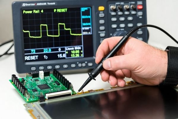
RESET should be measured on the real board, at the actual point where the LCD module receives the signal. This is the only reliable way to confirm startup timing and logic-level behavior.
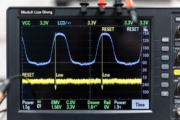
To measure RESET correctly, use an oscilloscope and probe the signal as close as possible to the LCD module connector or control pin. Capture RESET together with the module power rail and at least one related interface signal so the full startup sequence can be validated.
RESET should be measured at the LCD module connector, not assumed from the processor pin. The waveform observed at the host processor can differ from the actual module-side waveform because of trace length, connector impedance, pull resistors, level shifters, or passive filtering.
| Validation Task | Measurement Technique | What to Look For |
|---|---|---|
| Verify Power Sequence | Capture the module VCC rail and RESET on separate oscilloscope channels, triggering from power rise. | Confirm RESET stays in the active state until VCC is stable and within the valid operating range. |
| Measure Pulse Width | Use oscilloscope cursors or automatic timing measurements on the active RESET interval. | Ensure the active RESET duration meets or exceeds the minimum requirement in the controller or module documentation. |
| Check Release Timing | Capture RESET4 together with a related enable, clock, or command signal. | Confirm RESET is released only after the logic supply is stable and before command or video activity begins in the intended sequence. |
| Confirm Logic Levels | Measure the actual peak high and low voltages of RESET at the module side. | Verify the signal satisfies the required V_IH and V_IL thresholds under real operating conditions. |
A single successful startup capture is not enough. A design that passes once may still be marginal. Engineers should repeat the measurement over multiple power cycles, including cold starts and warm restarts, because startup timing can shift under different conditions. A single successful boot does not prove RESET robustness.
What Problems Can Incorrect RESET Logic Level Cause?
RESET timing is only part of the validation. Incorrect logic level can also prevent reliable initialization, and these failures are often more difficult to diagnose.
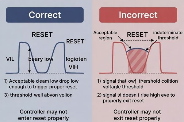
If the RESET logic level is incorrect, the module controller may never enter reset properly, may fail to exit reset, or may transition between unstable states. This is especially common in mixed-voltage designs, weak pull-up or pull-down networks, and GPIO-to-module level mismatches.
From an engineering perspective, logic-level problems often produce inconsistent symptoms. The module may sometimes start correctly and sometimes fail, or the behavior may vary with temperature, supply ramp rate, or board-to-board variation.
Failure to Enter Reset
For an active-low RESET input, the active low level must fall below the required V_IL threshold. If the low voltage is not sufficiently low, the controller may not enter reset cleanly. This can result in a partial reset condition, leaving internal logic in an undefined state. The startup behavior may then become erratic, with symptoms such as blank output, unstable initialization, or intermittent recovery only after repeated reboot attempts.
In both cases, engineers should validate not only the static logic levels but also the transition quality. A waveform that reaches the correct nominal voltage may still fail in practice if the edge is too slow, if overshoot causes instability, or if the GPIO default state briefly drives the module into an unintended sequence during power-up. If you need support reviewing the voltage-domain compatibility5 or startup behavior of your LCD module design, feel free to contact our engineering team at info@lcdmodulepro.com.
What Is a Practical Validation Workflow for RESET Robustness?
A robust RESET validation process should move from specification review to real-hardware measurement and then to stress validation under different startup conditions.
A practical RESET validation workflow begins with reviewing the module requirements, continues with oscilloscope verification on the actual hardware, and concludes with repeated power-cycle and environmental testing to confirm adequate design margin.
In practical LCD module integration, the goal is not only to make the module start once. The goal is to ensure that it initializes correctly every time, under real product conditions. A structured workflow is the most reliable way to achieve that.
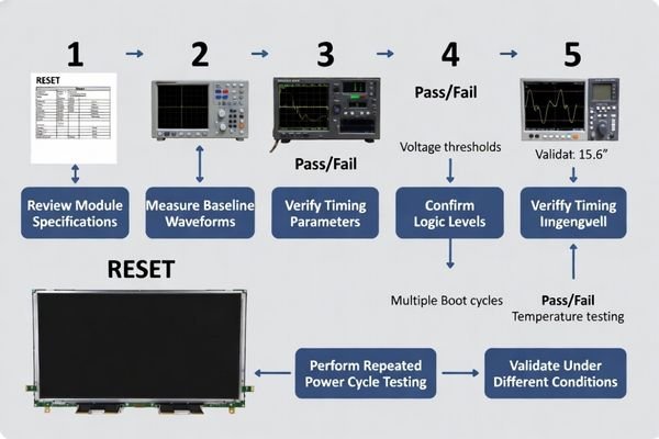
- Step 1: Review the Specifications. Confirm RESET polarity, minimum pulse width, delay requirements relative to power-up, and logic thresholds from the module or controller documentation. This step defines the criteria for all later measurements.
- Step 2: Capture Baseline Waveforms. Measure RESET, module power, and at least one related control or interface signal directly on the actual hardware. Verify that the observed timing and voltage thresholds match the intended startup sequence.
- Step 3: Perform Repetitive Power-Cycle Testing. Run repeated startup cycles to check for intermittent failures. A marginal RESET design may pass most of the time but still fail under repeated boot conditions.
- Step 4: Validate Under Environmental Stress. Repeat startup validation under low-temperature, high-temperature, and varied power-ramp conditions. This is especially important in industrial designs, where a sequence that works at room temperature may fail at the edge of the operating range.
- Step 5: Check Different Startup Scenarios. Test cold boot, warm reboot, slow power rise, and software restart behavior. These different conditions often reveal timing margin problems that do not appear in a single standard boot case.
This workflow helps engineers separate real panel issues from startup integrity problems caused by RESET timing, power sequencing, or logic-level mismatch. In actual hardware validation, repeated startup testing is often what reveals the hidden margin problem.
FAQ
Why does an LCD display module sometimes fail only during cold boot but work after reboot?
This often indicates a RESET or power-sequencing margin issue. During cold boot, supply ramp timing and GPIO default states may differ from a warm restart, causing the module to miss a valid reset condition.
Should RESET be checked at the processor pin or at the LCD module connector?
It should be checked as close as possible to the LCD module connector or control pin, because the actual waveform at the module side may differ from the processor output due to trace effects, pull resistors, or level shifting.
What is the most common RESET integration mistake?
One of the most common mistakes is using the wrong polarity or releasing RESET before the logic supply and internal controller are ready. Both can prevent correct initialization.
Can a logic level look correct on paper but still fail in real use?
Yes. A design may appear correct in the schematic, but real behavior can still fail because of threshold mismatch, slow edges, weak pull-ups, or GPIO default-state timing during startup.
How many reset cycles are enough during validation?
There is no single fixed number, but validation should include repeated power cycles and restarts under different voltage and temperature conditions to reveal marginal behavior.
Can software delay alone solve RESET timing issues?
Sometimes, but not always. Software delay can help if timing is the main problem, but hardware-level issues such as wrong voltage domain, poor edge quality, or unstable sequencing must still be corrected at the circuit level.
Conclusion
Validating RESET timing and logic level on an LCD display module requires both waveform measurement and startup-sequence verification on real hardware. A proper engineering review must confirm polarity, pulse width, delay relative to power, voltage thresholds, and the relationship between RESET release and the full initialization sequence. When RESET is validated at the correct measurement point and across repeated startup conditions, it becomes much easier to distinguish true module issues from integration faults caused by sequencing or logic-level mismatch.
At LCD Module Pro, we consistently treat RESET validation as a foundational step in LCD module reliability. By measuring the actual signal at the module side and checking it under repeated power cycles, different restart conditions, and environmental variation, engineering teams can significantly reduce startup instability and prevent difficult field failures. A well-validated RESET sequence is one of the clearest signs that an LCD module design is ready for dependable industrial and embedded use.
✉️ info@lcdmodulepro.com
🌐 https://lcdmodulepro.com/
-
Understanding RESET validation is crucial for ensuring reliable operation in LCD modules, preventing issues like blank screens and instability. ↩
-
Exploring power sequencing can help you grasp its impact on system stability and performance during startup. ↩
-
Understanding these errors can help engineers avoid pitfalls in their designs and ensure reliable startup behavior. ↩
-
Understanding the significance of measuring RESET at the module connector can enhance your design’s reliability and performance. ↩
-
Exploring voltage-domain compatibility is crucial for preventing design failures and ensuring system stability. ↩