Designing an LCD module for a device usually starts with a simple question: “What screen should we use?” In real projects, that question comes a little too late. By the time a team is asking only about size and resolution, the enclosure, mainboard, front panel, and user interface may already be limiting the display choices.
A practical LCD module design starts with the device: where it will be used, how much space is available, what signal the controller board can provide, how the user will interact with the screen, and how long the product must remain in production. The display has to fit the product system, not just a datasheet requirement.
In LCD module integration projects, the difficult cases are rarely caused by one dramatic mistake. More often, they come from small mismatches that were not checked early enough1: an FPC exits toward the wrong side, the cover glass leaves too little viewing area, the board only supports HDMI while the panel needs LVDS, or the enclosure has no room for a touch panel and adhesive stack.
A better starting point is to treat the LCD module as one part of the whole device. The display affects the front panel, cable path, power budget, thermal design, UI layout, assembly process, and long-term supply plan. Once those details are visible, the right LCD direction becomes much easier to define.
Start With Device Requirements, Not the LCD Specification
The first discussion should not begin with a panel model number. It should begin with the device itself. A control panel, measuring instrument, smart terminal, and transportation display may all need LCD modules, but they do not create the same design problem.
The device application should define the display direction. Operating environment, user workflow, available space, interface output, brightness requirement, touch structure, and lifecycle expectation should be understood before size, resolution, or interface is locked.
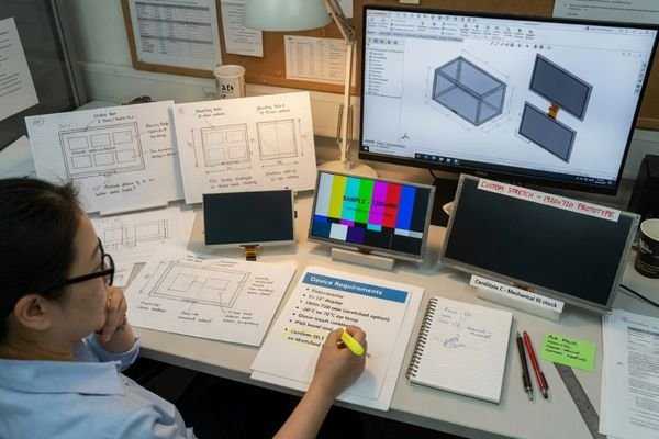
In early project discussions, our engineering team usually starts by asking for the application environment, target visible area, controller board interface, brightness requirement, touch structure, mechanical drawing, and lifecycle expectation. These inputs help decide whether the project can use a standard LCD module or needs a more customized direction.
For applications such as transportation systems, smart terminals, measuring equipment, and industrial control devices, the LCD module should be selected around the product environment and user workflow. A display that works well in one application may not be suitable for another if the enclosure, interface, brightness, or lifecycle requirements are different.
A short requirement sheet is usually enough to make the first review productive:
| Project Input | Why It Matters |
|---|---|
| Device application and use environment | Defines brightness, temperature, touch, and reliability priorities |
| Target visible area and enclosure space | Helps narrow size, aspect ratio, and mechanical options |
| Controller board output | Determines whether LVDS, eDP, MIPI, RGB, HDMI conversion, or a driver board is needed |
| Brightness and readability requirement | Affects backlight, optical stack, power, and thermal design |
| Touch and cover glass requirement | Changes thickness, reflection, bonding, and front-panel structure |
| Annual quantity and lifecycle expectation | Helps evaluate supply stability and customization feasibility |
This early information turns a vague display request into something that can be reviewed as an engineering problem.
Define the Mechanical Space and Display Area
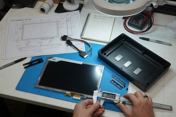
Mechanical fit is often the first real constraint. A module may meet the size target but still fail in assembly because the cable path, thickness, connector height, or viewing area does not match the enclosure.
Before selecting an LCD module, review the enclosure opening, active area, viewing area, outline dimension, module thickness, mounting method, connector position, and cable route. Mechanical mismatch is one of the fastest ways for a display project to lose time.
During mechanical review, our engineering team usually checks the enclosure opening, active area, viewing area, outline dimension, connector height, FPC exit direction, and cable bend space together. A display that fits by width and height may still fail if the connector or cable route conflicts with the internal structure.
Three terms are worth separating. The active area is the actual pixel area. The viewing area is what the user can see after the display is installed behind the front panel. The outline dimension is the full physical size of the module, including bezel, backlight frame, connector, FPC, and mounting structure.
Key Mechanical Considerations
- Front opening and active area: The opening should expose the intended display area without covering useful pixels or leaving an unwanted gap.
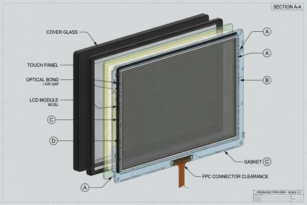
- Stack height: LCD, backlight, touch panel, cover glass, adhesive layers, gasket, and bracket all add thickness.
- Cable exit direction: The connector position and FPC direction must work with the mainboard location and internal cable path.
- Mounting method: Screws, brackets, adhesive, clips, or frame structures should be suitable for assembly and service.
- Front-panel design: Cover glass, gasket, touch sensor, and optical bonding can change the final viewing area and mechanical tolerance.2
A cable exit direction, connector height, or bezel overlap may look minor in CAD, but it can affect assembly, sealing, repair access, and production consistency.
Select Size, Resolution, and Aspect Ratio
After the mechanical space is clear, size, resolution, and aspect ratio can be selected with more confidence. These three choices should follow the UI layout, viewing distance, information density, and product structure.
Size, resolution, and aspect ratio should be chosen together. A higher resolution is not useful if the UI becomes too small, the controller board cannot support the signal, or the display shape does not match the device layout.
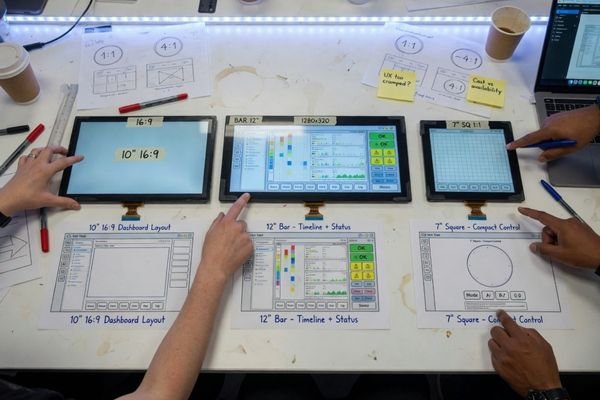
A simple status screen does not need the same pixel density as a dense equipment dashboard.3 If the display shows large text, icons, and basic values, a moderate resolution may be enough. If it shows charts, maps, multi-zone layouts, or small labels, more pixels and a better UI plan become important.
Aspect ratio also matters. A standard rectangular LCD may fit many products, but not all. Bar-type displays can work well for equipment status bars, transportation information, or narrow panel designs. Square displays may suit compact control interfaces. Round or special-shaped displays may be considered when the front panel design requires a non-standard format.
The practical question is not “What is the best LCD size?” It is “What screen format allows the user to read and interact with the device comfortably inside the available mechanical space?”
Match the LCD Interface With Your Controller Board
Interface compatibility is one of the most common reasons a display project slows down. An LCD module is not usually a plug-and-play monitor. Many modules use panel-level interfaces that must be matched with the controller board.
Before locking the LCD module, confirm the display interface, pinout, signal timing, logic voltage, backlight power, touch interface, and bandwidth requirements. A matching connector shape does not mean the electronics are compatible.
Before recommending an interface configuration, our engineering team usually compares the controller board output with the LCD panel interface, pinout, timing, logic voltage, backlight power, and touch interface. Many integration issues appear not because the panel is wrong, but because one electrical detail was not confirmed early enough.
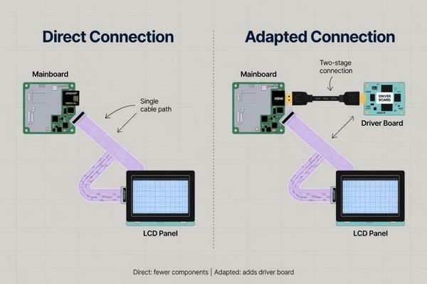
Common panel interfaces include LVDS, eDP, RGB, and MIPI DSI.4 Some controller boards provide these signals directly. Others only output HDMI, DisplayPort, or another standard video signal, which means a driver board or adapter board may be required.
Interface review is more than naming the interface. The following items usually need to be checked before the module and mainboard are finalized:
| Interface Item | What Needs to Be Checked |
|---|---|
| Pinout | Connector definition, lane assignment, and signal order |
| Timing | Resolution, refresh rate, sync parameters, and panel timing support |
| Voltage | Logic voltage, backlight voltage, current, and enable/PWM control |
| Bandwidth | Whether the interface can support the target resolution, color depth, and refresh rate |
| Touch interface | I2C, USB, controller location, firmware, and cable routing |
| Driver board need | Whether the system requires HDMI-to-LVDS, HDMI-to-eDP, or another conversion path |
When interface details are not clear, it is better to Discuss your custom display project before the controller board and LCD module are finalized. Early interface review can prevent flicker, no-image problems, unstable signals, or late-stage hardware changes.
Plan Brightness, Touch, Power, and Thermal Requirements Together
Brightness, touch, power, and thermal design are connected. Changing one of them often changes the others, especially in outdoor, sealed, compact, or long-running equipment.
A readable and reliable display depends on the full display stack: LCD panel, backlight, touch sensor, cover glass, bonding method, power budget, and thermal path. These items should be reviewed together, not as separate decisions.
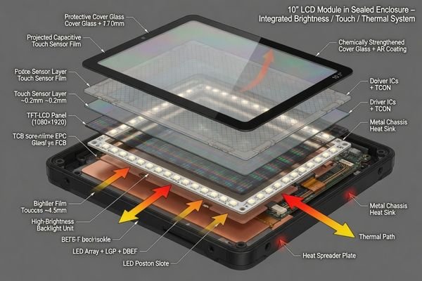
When brightness or touch integration is involved, our engineering team usually reviews the full front stack: LCD panel, backlight, touch sensor, cover glass, bonding method, power budget, and thermal path. This helps avoid choosing a display that looks correct in a sample test but becomes difficult to use inside the final enclosure.
A high-brightness LCD module may improve visibility, but it also increases power consumption and heat. If the device is sealed or fanless, the enclosure must have a way to move that heat away from the backlight and panel. A display that looks good on a bench may behave differently after several hours inside the final housing.
Touch integration adds another layer of trade-offs. PCAP touch, cover glass, air gap, optical bonding, and surface coating all affect reflection, thickness, durability, and perceived brightness. A thicker cover glass may be needed for protection, but it can reduce readability if the optical structure is not planned well.
When brightness or outdoor readability becomes part of the project, you can Explore high brightness display modules to understand common module directions. Brightness, touch, optical structure, power budget, and enclosure conditions should be evaluated together before deciding whether the project needs a standard module, optical bonding, custom cover glass, or a more integrated LCD module design.
Validate the LCD Module Before Production
A custom LCD module project is not complete when the first sample lights up. A working sample only proves that the basic electrical path is possible. It does not prove that the module is ready for production.
Before production, the LCD module should be validated inside the real product system, with the final enclosure, controller board, cable path, touch structure, brightness target, thermal condition, and operating environment. Bench testing alone is not enough.
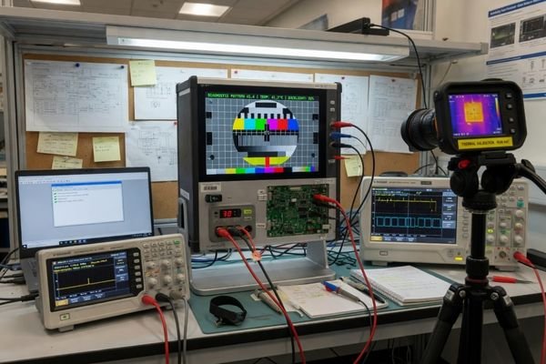
Validation should check mechanical fit, interface stability, touch response, optical performance, thermal behavior, and assembly consistency. The display should be tested not only when it first powers on, but also after extended operation, temperature exposure, and repeated user interaction.
Production planning should also cover:
- BOM stability: Key components need a realistic lifecycle and supply plan.
- Assembly practicality: Cables, connectors, brackets, and bonding steps should be suitable for production handling.
- Batch consistency: Brightness, color, touch response, and interface stability should remain controlled across batches.
- Documentation: Drawings, interface definitions, test requirements, and approval criteria should be clear before volume supply.
A structured validation process reduces the risk of redesign after tooling, pilot build, or early production. For projects that need deeper review, custom LCD module engineering can help connect design requirements with sample verification and production planning.
LCD Module Design FAQ
What information is needed to design a custom LCD module?
Useful starting information includes the device application, target display size, visible area, resolution, interface type, brightness requirement, mechanical drawing, touch requirement, operating environment, estimated annual quantity, and expected production schedule.
Can I use a standard LCD module instead of a custom one?
Yes. A standard LCD module is suitable when it fits the enclosure, interface, brightness, touch, temperature, and lifecycle requirements. Customization becomes necessary when the product has fixed mechanical space, a non-standard aspect ratio, special brightness needs, interface constraints, or long-term supply requirements.
Does an LCD module support HDMI input directly?
In most cases, no. LCD modules usually use panel-level interfaces such as LVDS, eDP, RGB, or MIPI DSI. HDMI input normally requires a driver board that converts the signal according to the panel’s timing, voltage, and backlight requirements.
How do I choose the right brightness for my device?
Brightness should be selected according to the use environment. Indoor products may only need standard brightness, while outdoor or semi-outdoor products may require high brightness, optical bonding, anti-glare treatment, or anti-reflective cover glass. Thermal and power limits should also be reviewed.
When should I involve an LCD module engineer?
It is best to involve an engineer before the mechanical design and controller board are fully fixed. Early review is especially important for custom size, special interface, high brightness, touch integration, sealed structure, wide temperature operation, or long lifecycle projects.
Conclusion
Designing an LCD module for your device is a system-level engineering task. The right display is not simply the one with the strongest individual specification. It is the one that fits the enclosure, connects reliably with the controller board, supports the UI, meets readability and touch requirements, and remains practical for validation, production, and long-term supply.
Not sure which LCD module design fits your project? Start by preparing the application, target size, resolution, interface, brightness requirement, mechanical drawing, touch requirement, operating environment, and production plan. Our engineering team can help review the display requirements before the module is finalized.
→ Start your custom display project
✉️ info@lcdmodulepro.com
🌐 https://lcdmodulepro.com/
-
Coneksion. “10 Common Reasons Integration Projects Fail.” ↩
-
Maple Systems. “What Is Optical Bonding for Industrial Monitors?.” ↩
-
Android Developers. “Support different pixel densities.” ↩
-
Riverdi. “Interfaces in LCD Display Modules: SPI, I2C, LVDS, MIPI, VX1, eDP and Others.” ↩