Bar displays provide high information density in narrow footprints ideal for industrial control panel integration while supporting operator scanning and cabinet space constraints.
Bar displays deliver optimal information density for industrial control panels by providing multi-channel status, alarms, trends, and progress indicators in narrow, panel-friendly footprints that align with cabinet door constraints while supporting quick operator scanning across multiple zones without requiring larger cutouts or full HMI screens.
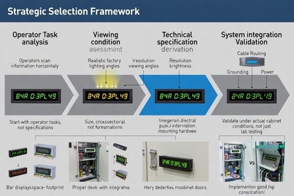
In my LCD display module integration work at MEIDAYINGNUO, I’ve found that bar displays succeed when they are treated like long-life instrument indicators—not like cropped monitors. A good selection process starts with the operator task (what must be read at a glance), then locks the viewing conditions (distance, angle, glare sources), and only then chooses size/resolution and brightness/reflection behavior that remain legible in real factory lighting. Next, validate the system realities that often decide field stability: cable/FPC routing near noisy harnesses, grounding paths inside the cabinet, and power-noise coupling from switching supplies. Finally, protect long-term consistency with lifecycle terms—backlight aging expectations1, static-content validation, and change control—so production lots and replacement parts behave the same.
Why are bar displays popular in industrial control panels?
Bar displays optimize information presentation within industrial panel space constraints while supporting efficient operator workflow patterns.
Bar displays fit industrial control panels by delivering high information density in narrow, panel-friendly footprints that accommodate multi-channel status displays, alarm indication, trend visualization, and progress monitoring without forcing larger cutouts or full HMI screens, while supporting operator scanning patterns across multiple zones and aligning with cabinet door space constraints.
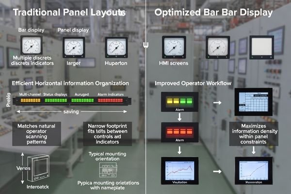
From an engineering standpoint, bar displays work because they match how operators scan: left-to-right across channels, alarms, and trends. They also match how panels are built: long windows, nameplates, and limited door real estate. The key is to optimize them for clarity, durability, and consistency—because small readability or uniformity issues are more obvious on long, thin layouts.
Information Density Optimization
Bar displays maximize useful display area within constrained panel cutouts by organizing information horizontally to match operator scanning patterns and multi-channel monitoring requirements. To make that density usable, define what must be “instant readable” (alarm states, key numbers, channel labels) and reserve a consistent layout rhythm with separators and safe margins. Long-axis uniformity matters because edge zones are still read; avoid designs where critical numbers live in regions likely to be shadowed by bezels or affected by gradients. Treat the bar display as a dedicated status instrument, not a general UI canvas.
Mechanical Integration Advantages2
The long, narrow form factor aligns naturally with nameplate layouts, bezel window designs, and cabinet door constraints typical of industrial control panel architectures. It can reduce cutout height and help fit indicators into tight panel bands, but it also demands disciplined stack-up control. Plan for mounting points, gasket compression, and bezel shadowing so the enclosure does not introduce warpage or edge shading along the length. If a cover lens or touch layer is used, define the assembled optical stack early so reflections and contrast remain acceptable in the installed viewing angle.
What readability targets should you define first?
Readability specifications must account for actual viewing conditions including distance, ambient lighting, and information density requirements specific to bar display applications.
Define readability based on actual panel usage including viewing distance, typical viewing angles, ambient factory lighting conditions, and UI information density requirements. Bar display legibility depends on pixel density relationship to font sizing, contrast performance under glare conditions, and uniformity across the long axis to prevent operator misreading of edge regions under real factory lighting rather than laboratory conditions.
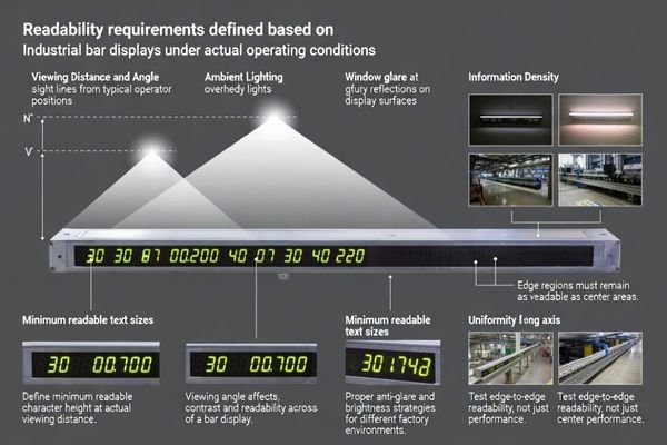
Based on the projects I support with industrial HMI optimization, the biggest readability misses happen when teams validate in a quiet lab instead of the installed panel. Define a minimum readable character height at the real viewing distance, then confirm the UI is still readable at the typical off-axis angle. Set glare expectations using real lighting conditions (overhead lights, sunlight spill, reflective cabinet doors), because reflection control often matters as much as raw brightness. Finally, specify long-axis uniformity3 and “critical zones” so key alarms and numeric readouts remain clear at the edges, not just in the center. If the shipped product uses a cover lens or touch stack, tie acceptance to the assembled condition (or define a correlation method) to avoid false rejects and field surprises.
How do you balance size, resolution, and UI layout on a bar display?
Optimal bar display configuration balances information clarity with practical constraints while avoiding excessive specification that increases system complexity.
Balance size, resolution, and UI layout by starting from UI grid requirements including channel count, minimum readable font size at viewing distance, and separator needs, then selecting resolution supporting clean edges and stable grayscale for thin elements while avoiding over-specification that increases bandwidth and processing burden, and planning for edge-to-edge content with safe margins for critical information.
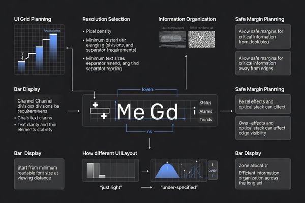
When I troubleshoot bar display readability issues, the root cause is often a mismatch between pixel geometry and UI scaling: fonts that looked fine in a design tool become cramped, low-contrast, or “shimmery” on the installed panel. Start with the UI grid and minimum character size, then choose a resolution that makes digits and thin separators clean without forcing unnecessary bandwidth and validation burden. Also plan safe margins for edge content, because bezels, lens shading, and mechanical tolerances can affect readability near the ends.
| Display Length | Typical Resolution | UI Application |
|---|---|---|
| 12.3" Bar | 1920×200 to 1920×360 | Multi-channel monitoring, trend strips |
| 15.6" Bar | 1920×360 to 1920×480 | Complex status arrays, alarm management |
| 21.5" Bar | 1920×540 to 1920×720 | Large-scale process monitoring, control dashboards |
Resolution selection should support clean text rendering at required viewing distances while avoiding bandwidth overhead that complicates system integration and validation. The examples above are illustrative only; final values should be confirmed against your actual UI, viewing distance, and module specifications.
For comprehensive bar display UI optimization and readability validation4 support, engineering teams can contact info@lcdmodulepro.com during interface design phases.
What industrial risks are specific to bar displays?
Bar displays face unique reliability challenges related to their form factor, usage patterns, and integration requirements in industrial environments.
Specific risks include image retention from static or semi-static content during long operating hours, brightness drift and uniformity changes over time being more visible than on larger screens, mounting stress and gasket compression sensitivity affecting long-axis uniformity, and EMI/ESD vulnerability from proximity to noisy harnesses and switching supplies in control panels.
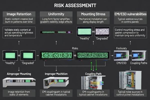
I’ve observed that bar display issues are rarely “one big failure” on day one—they are slow margin problems. Static UIs can reveal retention over time, long-axis gradients become more noticeable as backlights age, and small mechanical or noise-coupling changes can trigger intermittent flicker or re-sync events. Early validation under realistic stress (temperature, cabinet EMI, mounting stress) prevents most production surprises.
Static Content Challenges
Extended display of static control panel interfaces increases image retention risk and accelerates backlight aging, requiring specific validation and derating strategies for industrial duty cycles. Define the expected static-duty pattern5 (what stays on-screen for hours), then validate retention and recovery under realistic brightness and temperature, not just at room conditions. Tie the operating brightness target to lifetime goals so you don’t overdrive the backlight for “extra pop” that is not needed in the real cabinet. When the application allows, simple UI behaviors (periodic subtle refresh or minor element movement) can reduce long-term stress without changing operator workflow.
Mechanical Sensitivity Factors
The elongated form factor makes bar displays more sensitive to mounting stress, enclosure flatness, and gasket compression variations that can create visible uniformity problems across the display length. Control stack-up with defined mounting points, torque limits, and gasket compression targets so the module isn’t warped during assembly. Account for bezel shadowing and lens-edge shading, especially near the ends where gradients are easiest to spot. If you bond a cover lens or touch stack, specify process controls (adhesive thickness, curing, pressure distribution) to avoid mura-like artifacts. Validate under vibration and service actions so the visual result remains stable over time.
How to choose an LCD module strategy for bar displays in control panels?
Bar display module selection requires systematic evaluation of operator requirements, system integration constraints, and lifecycle reliability factors.
Module strategy should be driven by operator task analysis and enclosure constraints, then validated through interface and reliability budgeting including critical viewing zone definition, minimum legible character sizing, brightness and reflection performance under factory lighting, timing headroom across cable routing, grounding proximity to PLC wiring, and mechanical integration controlling mounting and optical stack effects on uniformity.
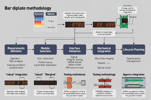
Based on my experience with control panel bar display projects, the most reliable strategy is to treat selection as a system decision. Start by defining critical viewing zones and readability targets under real lighting, then choose size/resolution that supports the UI without forcing extreme scaling. Validate the interface with timing headroom across the real cable/FPC route and grounding plan, and treat EMI/ESD as a system-level outcome—not a module-only property—by planning routing, shielding, and power-noise control. Finally, lock lifecycle terms (backlight aging expectations, static-content validation, and change control) so later lots and spares remain consistent.
| Application / Scenario | Usage Pattern | Display Requirements | Recommended Model | Key Integration Considerations |
|---|---|---|---|---|
| Compact Process Monitor | Multi-parameter status display | Moderate brightness, high uniformity | BU123X | Mounting stress control, EMI shielding, static content validation |
| Extended Control Interface | Operator interaction and monitoring | Touch-friendly sizing, wide viewing angle | BU156X | Interface timing margin, thermal management, gasket compression |
| Multi-Zone Dashboard | Large-scale process overview | High information density, color coding | BU173X | Signal integrity optimization, mechanical precision, lifecycle planning |
| Wide Process Display | Comprehensive system monitoring | Maximum information presentation | BU215X | EMI hardening, optical uniformity control, service accessibility |
| Ultra-Wide Control Center | Mission-critical operations | Maximum viewing area, redundancy planning | BU320S | System-level integration, reliability validation, change control |
FAQ
Do bar displays always require higher brightness than standard modules?
Not always. The right target depends on ambient light and reflection control; a well-managed anti-reflection strategy can outperform brute-force brightness while extending backlight life.
How do you prevent image retention on bar displays showing static status screens?
Specify retention limits, validate under realistic static duty cycles, and ensure the driving scheme and operating brightness are chosen to minimize long-term stress; UI strategies can help when the application allows.
Should acceptance be based on the bare module or the assembled cover lens/touch stack?
Base it on how the product is judged in reality. If the shipped product is evaluated assembled, align procurement and inspection to the assembled condition or define a correlation method.
What interface pitfalls are common with long, thin displays?
Marginal bandwidth/timing, long FPC routes, connector variability, and poor grounding can cause intermittent flicker or re-sync events, especially in noisy cabinets.
How do mechanical tolerances affect long-axis uniformity?
Small warpage, uneven gasket compression, or bezel shadowing can create visible gradients or edge shading along the length, so mounting and stack-up control are critical.
What should be included in lifecycle and change-control terms for bar displays?
Define backlight lifetime at the required operating brightness, require notification/re-approval for changes to backlight and optical films, and keep a master reference for lot-to-lot consistency.
Conclusion
Choosing bar displays for industrial control panels requires prioritizing long-term readability reliability over specification maximization, starting from operator viewing scenarios and UI layout requirements to select appropriate size, resolution, and brightness performance that remains clear under factory lighting conditions. Success depends on budgeting interface margin across actual cable routing and EMI environments while controlling mechanical stack-up to maintain long-axis uniformity, combined with lifecycle terms covering backlight longevity, static content validation, and material change control for consistent performance across production lots and service life.
MEIDAYINGNUO can support bar-type LCD module selection and integration validation for industrial control panels, including readability checks under factory lighting, system-level EMI/ESD risk review, and long-run stability planning for static-content use. Contact our technical team when bar display applications need clearer specifications, production-representative validation setups, and lifecycle controls to reduce field risk.
✉️ info@lcdmodulepro.com
🌐 https://lcdmodulepro.com/
-
Learn about backlight aging expectations to ensure your LCD displays maintain quality over time. ↩
-
This resource will provide insights into how bar displays can be effectively integrated into control panels, enhancing functionality and design. ↩
-
Exploring long-axis uniformity helps ensure that critical information is visible across the entire display, enhancing safety and efficiency. ↩
-
Exploring readability validation techniques can enhance your design process and improve user interface effectiveness. ↩
-
Understanding static-duty patterns is crucial for optimizing display performance and longevity, ensuring minimal image retention. ↩