Bezel design directly influences visible area calculations by defining the window edge overlap that determines how much pixel content remains accessible to users after mechanical integration.
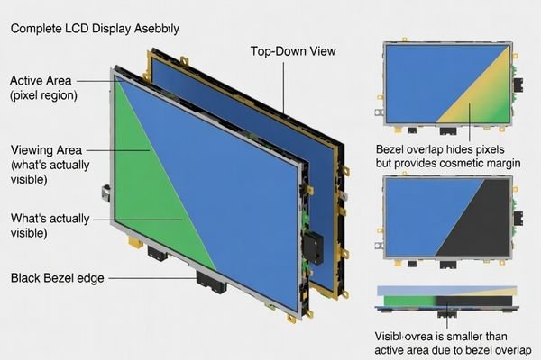
A bezel is the frame around the window that defines what users perceive as the screen edge. Because it overlaps the stack to hide borders, adhesives, and tolerance variation, it can also hide usable pixels. That’s why visible area is an assembly result, not just a panel spec, and bezel geometry must be included in calculations.
In LCD display module integration, teams often “lose” visible pixels1 late in development because bezel overlap was treated as styling rather than a hard boundary for content. A good approach is to treat bezel, window, and masking as a single system: define what must remain visible for UI, then design overlap and margins to absorb normal manufacturing and assembly variation. This reduces rework, prevents edge clipping, and keeps the final product consistent across builds.
What is a bezel in an LCD display module integration?
Bezel represents the framing structure that defines window boundaries, provides mechanical location, and establishes the user-perceived edge of the display area.
In LCD display module integration, a bezel is the mechanical and cosmetic frame around the window opening. It may be part of the enclosure, a separate frame, or a bonded trim, and it often overlaps the display stack to hide non-display borders, adhesives, and assembly variation. Because it defines the perceived screen edge, bezel geometry sets the practical boundary for visible content.
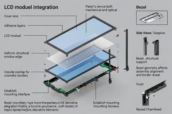
A bezel is rarely “just decoration.” Mechanically, it can locate the cover lens and constrain how the module sits inside the product. Optically, it sets the window edge that the human eye uses to judge alignment and border symmetry. In many designs, bezel width and corner shape are chosen specifically to hide black masks, glue lines, and small positional drift without exposing non-display regions. Because bezel decisions directly shape what remains visible, they must be coordinated with UI margins and tolerance plans early—not after industrial design is frozen.
Mechanical Functions and Integration Role
Bezel features often become part of the locating and retention strategy: they can define the opening, provide seating surfaces, support gasket placement, and control reveal around the cover lens. They also create practical keep-outs for adhesive fillets, vents, and fastening tools. If these constraints are not defined, the assembly may “work” but only with extra force, non-repeatable alignment, or inconsistent border reveal. Good mechanical planning ties bezel references to a clear datum scheme so window location stays consistent from prototype to production and during service rework.
Optical Boundary Definition and User Perception
From the user’s perspective, the bezel is the screen boundary, even though pixels exist underneath. If overlap is too wide or corners are too aggressive, UI content near the edge can be clipped first at corners. If overlap is too narrow, the product may expose black mask edges or adhesive lines and look misaligned when tolerances stack. Treat bezel overlap and corner geometry as optical parameters2: define the intended border reveal, then reserve content-safe margins so critical UI elements never approach the “hidden-by-bezel” region.
Why does bezel design change visible area calculations?
Bezel overlap directly reduces the effective visible pixel area available for content display, requiring systematic calculation methodology that accounts for mechanical constraints.
Visible area is the portion of pixels left unobstructed after bezel overlap, masking, and the cover-lens stack are applied. Wider overlap can hide borders and variation, but it reduces usable pixels and may clip UI if margins are tight. Narrow overlap increases visibility but can expose masks or glue lines. Accurate calculations must include overlap, corner radii, drift, and content-safe margins.
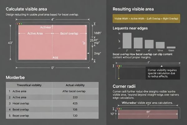
A common mistake is calculating visible area from a drawing that only lists panel size, then discovering later that the bezel or ink mask hides part of that region. The calculation must reflect the final stack: bezel edge, cover lens mask, and any adhesives or gaskets that require clearance. Corner behavior matters because corners are where small shifts become obvious and where clipping often occurs first. The safest workflow is to set a content-safe area for UI, then verify that the resulting visible area3 remains stable under worst-case tolerance extremes and viewing angles.
How do you define the right reference: active area, viewing area, or window?
Proper reference definition requires clear distinction between active area, viewing area, and window opening to prevent calculation errors and design confusion.
Use active area as the pixel boundary, viewing area as what is actually visible through the full stack, and window as the physical opening defined by bezel and cover lens. For UI, start from active area and apply a content-safe margin for overlap and tolerance. For mechanics, use the window/bezel limits. Mixing these references is a top cause of unexpected clipping.
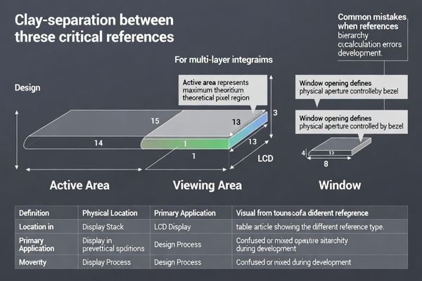
Reference confusion often happens across teams: UI may assume the full pixel boundary is usable, while mechanical design assumes the window opening defines what users will see. The resolution is to explicitly assign each reference to a decision: UI layout uses a content-safe area; mechanical layout uses window and bezel geometry; final acceptance uses measured viewing area on real builds. If drawings and specs clearly label which reference is being used, you avoid “paper visibility” that the assembled product cannot deliver.
| Reference Type | Definition | Primary Use | Key Considerations |
|---|---|---|---|
| Active Area | Pixel array boundary | Content layout and UI design | Maximum theoretical display region |
| Viewing Area | Optically visible region through stack | User experience validation | Accounts for cover lens and masking effects |
| Window Opening | Physical bezel-defined aperture | Mechanical design and assembly | Includes bezel overlap and tolerance margins |
| Content Safe Area4 | UI-safe region within viewing area | Interface element placement | Includes margins for bezel variation and alignment |
Systematic reference definition ensures that optical requirements, mechanical constraints, and user interface needs are managed consistently while preventing calculation errors that lead to clipped content or exposed non-display regions during production.
Manufacturing and assembly variations can amplify bezel-related visible area errors through cumulative positional drift and geometric misalignment effects.
Bezel-related errors increase when layers can shift: cover-lens printing, bezel fabrication, adhesive thickness/creep, gasket compression, and module placement tolerance. Small translation and rotation become obvious at corners, especially with mismatched radii or tight UI margins. Z-height parallax can change perceived border width by angle. Budget translation and rotation, set overlap to hide variation, and validate on real builds.
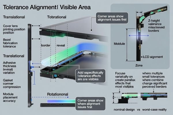
Variation is rarely a single number; it is a stack of small shifts across multiple parts and processes. Printing tolerances can move the mask edge, adhesive thickness can change where parts settle, and gasket compression can drift over time or temperature. If the UI runs close to the edge, these small shifts translate into visible asymmetry or clipping. Corners amplify the problem because rotation creates the largest offsets there, and radius mismatches can cause “early corner bite.” To manage this, allocate tolerance to both translation and rotation and choose bezel overlap that can absorb normal drift while protecting the content-safe area.
I’ve observed that tolerance accumulation5 affects visible area more dramatically at corners and edges where small misalignments become visually obvious, requiring comprehensive stack-up analysis and assembly control to maintain consistent appearance. For complex bezel integration requiring systematic tolerance analysis and visible area optimization during LCD module development projects demanding precise optical coordination and cosmetic appearance management, engineering teams can contact info@lcdmodulepro.com when bezel alignment challenges require specialized expertise in optical stack design and manufacturing variation control.
Translation and Positional Drift Effects
Positional drift comes from multiple contributors: cover lens print placement, bezel molding/machining variation, adhesive thickness, and assembly repeatability. Even if each contributor is “small,” the combined worst case can create uneven border reveal along straight edges and visible shifts at corners. Plan for this by defining clear datums, measuring drift on early builds, and keeping a realistic content-safe margin so critical UI elements never depend on perfect alignment. If you must go narrow, use overlap strategically to hide predictable variation.
Rotation and Angular Misalignment Impact
Rotation is often underestimated because teams focus on X/Y offsets. A small angular error can look acceptable near the center but becomes noticeable at corners where the effective offset is largest. Rotation also interacts with corner radii: mismatched geometry can cause one corner to clip earlier than others. Use locating features and assembly processes that constrain rotation, and verify rotation limits with representative builds. When validating, inspect corner reveal and corner clipping first—they are the quickest indicators of angular misalignment.
How do you plan bezel and window geometry for custom LCD modules?
Effective bezel and window planning requires systematic approach balancing visible area optimization with tolerance management and cosmetic appearance requirements.
Start from the user-visible requirement: define the UI content-safe region you must keep visible, then set bezel overlap, mask width, and corner geometry to hide non-display borders and normal variation. Use a consistent datum scheme for window, bezel, and module, and reserve keep-outs for adhesive and tools. Validate with early samples to confirm stable viewing area across tolerance, temperature, and rework.
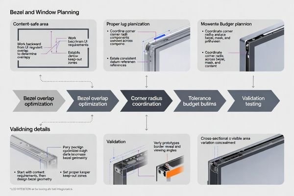
A practical planning method works backward from what users must see. First, define the minimum visible region for UI and apply a content-safe margin based on expected drift and corner behavior. Next, choose bezel overlap and mask design that can hide black borders and glue lines while still preserving the content-safe region. Then ensure mechanical references are consistent: if the cover lens mask references one origin and the bezel references another, the product will show it. Finally, prototype early with production-intent processes because adhesive creep, gasket compression, and real assembly handling often change the true viewing area more than nominal CAD suggests.
Design Strategy and Requirements Analysis
Content Priority Definition:
Define which UI elements must remain visible under worst-case conditions and set a content-safe margin6 that accounts for bezel overlap, corner radii, and measured drift from early builds.
Tolerance Budget Allocation:
Build a tolerance budget that includes cover-lens print tolerance, bezel geometry, adhesive thickness, gasket compression, and module placement variation, and allocate overlap to hide normal variation without sacrificing critical content.
Cosmetic Integration Planning:
Coordinate corner radii and edge profiles across bezel, window, and mask so the product has consistent border reveal and avoids early corner clipping or uneven corner appearance.
Validation and Optimization Process
Prototype Development:
Build early samples using production-intent parts and processes to validate viewing area, border reveal, and corner behavior before committing to final tooling.
Assembly Process Verification:
Confirm that adhesive application, gasket compression, and locating features produce repeatable alignment and stable overlap after cure, thermal cycling, and service rework.
Optical Performance Testing:
Check visibility under glare and off-axis viewing, and verify that parallax does not create unacceptable perceived border width changes at typical user angles.
Customization Strategy Assessment:
When margins are tight, customization of bezel, cover lens masking, and locating features is often the cleanest way to achieve a narrow, consistent look without risking clipped content.
FAQ
Is bezel the same as the window cutout?
Not exactly. The window cutout is the opening size, while the bezel is the framing structure that defines and often overlaps that opening; together they determine what is actually visible.
Can a bezel hide non-display borders without reducing usable content?
Only if the UI keeps a content-safe margin. If content is placed too close to the edge, bezel overlap will clip it even if the pixel area exists.
Why do corner radii cause visible area surprises?
If bezel/window corner radii don’t match the cover lens mask and the UI layout, the corners may clip earlier than expected or reveal uneven border widths.
Should visible area be calculated from active area or viewing area?
For UI safety, start from active area and apply margins for bezel overlap and tolerance; for user perception, viewing area through the full stack is the final check.
How do adhesives and gaskets affect bezel alignment?
Adhesive thickness and creep, plus gasket compression, can shift the window relative to the module and change border reveal, especially over temperature and time.
When is customization the best option?
When you need tight cosmetics, limited margin, specific corner geometry, or high glare control; customization aligns bezel, cover lens, and masking to real tolerances.
Conclusion
Bezel design directly impacts visible area calculations by establishing the mechanical and optical boundaries that determine usable pixel content after integration assembly. Effective bezel planning requires systematic approach treating bezel overlap as design constraint while coordinating active area specifications, viewing area optimization, and window geometry to prevent content clipping and maintain cosmetic appearance. By defining clear references for active area versus viewing area versus window boundaries, managing tolerance stack-up effects, and validating visible area stability through representative prototype testing, teams achieve reliable visible area predictions that support both functional requirements and aesthetic objectives.
MEIDAYINGNUO provides comprehensive bezel integration and visible area optimization services for custom LCD module applications requiring systematic geometry planning, tolerance analysis, and optical coordination for complex display integration projects. Our engineering team offers specialized expertise in bezel design methodology, visible area calculation optimization, tolerance management, and prototype validation ensuring LCD modules deliver reliable visible area performance while maintaining cosmetic quality and manufacturing feasibility throughout extended product lifecycles. Contact our optical integration specialists when bezel challenges require expert geometry planning and systematic visible area analysis for successful custom integration outcomes.
✉️ info@lcdmodulepro.com
🌐 https://lcdmodulepro.com/
-
Understanding visible pixels is crucial for ensuring UI elements are displayed correctly, preventing costly rework. ↩
-
Exploring optical parameters can enhance UI design, ensuring that critical elements are visible and improving overall user satisfaction. ↩
-
Understanding visible area is crucial for accurate design, ensuring that important content isn’t obscured by bezels or masks. ↩
-
Understanding the Content Safe Area is crucial for effective UI design, ensuring that all elements are displayed correctly across devices. ↩
-
Understanding tolerance accumulation is crucial for maintaining product quality and appearance in manufacturing processes. ↩
-
Understanding content-safe margins is crucial for ensuring that essential UI elements remain visible, enhancing user experience. ↩