Selecting an LCD display module for constrained installation spaces requires systematic mechanical validation, thermal management, and interface optimization to avoid costly redesign cycles.
Limited installation space constrains not only the display’s active area, but the complete mechanical envelope including module thickness, bezel dimensions, FPC routing space, connector clearance, and mounting requirements. Success depends on validating the full stack-up early and balancing readability needs with thermal and power limitations.
When I troubleshoot field issues on compact products that integrate LCD display modules, I often find that teams focus on the visible screen area while underestimating the hidden mechanical requirements. FPC bend radius, connector mating height, and tolerance accumulation1 can easily consume the last few millimeters of available space, forcing expensive enclosure modifications or module changes late in development. A disciplined approach validates the complete constraint hierarchy before committing to tooling.
What does "limited installation space" really mean for an LCD display module?
Limited installation space encompasses far more than the visible cutout dimensions.
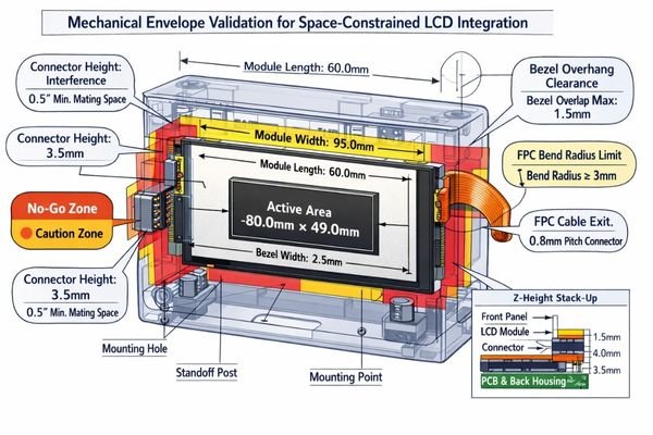
True space constraints include the complete mechanical envelope: bezel clearance requirements, module thickness including backlight housing, FPC bend radius and exit direction, connector mating height, mounting boss locations, standoff clearances, and any protective cover lens or touch stack thickness.
In my LCD display module integration work at MEIDAYINGNUO, I establish three critical boundaries first: maximum Z-height including gasket compression and thermal expansion, keep-out zones around mounting features and cable routing, and the actual viewing window exposed on the front panel. These boundaries determine whether we should prioritize thinner modules, narrower bezels, alternative aspect ratios, or custom FPC orientations to avoid mechanical conflicts.
Z-Height and Stack-Up Constraints
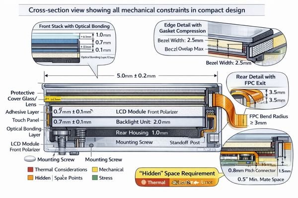
Module thickness varies significantly across the backlight area, connector region, and mounting points. To make this verifiable (not just “looks OK in CAD”), I work from a cross-section stack-up with worst-case tolerances: front cover (if used) and adhesive thickness, any gasket compression range, module bezel seating plane, backlight housing high points, and the closest chassis feature behind the module. A practical pass/fail rule is to reserve real assembly margin in Z for compression and part variation rather than designing to nominal; if your measured clearance is only “paper-thin,” it typically disappears in real builds. The most common mistake I see is measuring thickness at the module center while the interference occurs at an edge (backlight rim, stiffener, or connector area), so I always confirm the maximum local thickness and the actual contact points, then document where the assembly is allowed to touch and where it must not.
FPC Routing and Connector Clearance
FPC bend radius requirements2 and connector mating height often determine feasible installation approaches. I validate this with a physical routing sketch and keep-out volumes, not just a line in CAD: define the FPC exit direction, the minimum bend radius along the fold, and the required “service space” for connector mating and tool access. A useful criterion is whether the FPC can be routed without forcing a sharp crease or constant strain at the fold—if the design relies on a tight fold to fit, it tends to become a fatigue and intermittency risk over temperature cycling and vibration. The most common integration errors are (1) assuming the connector can mate with near-zero insertion space, (2) ignoring stiffener length that prevents bending where you want it to bend, and placing ribs or screws in the FPC sweep area so the cable is pinched during assembly. If the enclosure is fixed, I usually regain feasibility by adjusting the FPC exit orientation, providing a controlled bend support feature, and ensuring the connector is reachable for assembly and rework.
Which mechanical constraints should you verify first to avoid redesign loops?
Early mechanical validation prevents costly late-stage discoveries and enclosure modifications.
I verify the mechanical stack-up progression: front cover and gasket layers, LCD module bezel and active area positioning, backlight thickness distribution, FPC routing and bend radius requirements, connector clearance, and chassis mounting features. Tolerance accumulation analysis ensures real assembly margins match design assumptions.
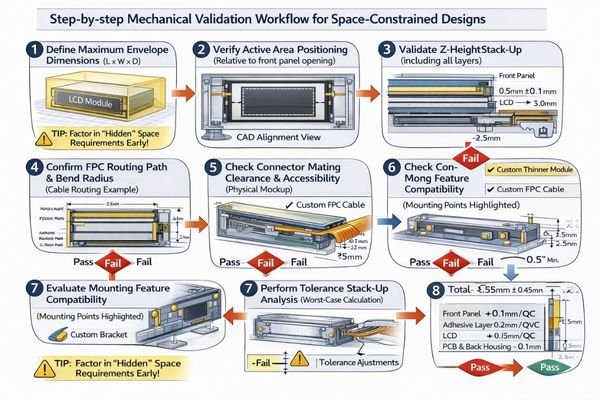
From an engineering standpoint, I usually start with FPC fold geometry and connector mating requirements because these create the most frequent integration conflicts. Small variances in plastic ribs, metal brackets, and foam gaskets can eliminate the final 0.5-1.0mm of clearance that appeared available in CAD models. When enclosure geometry is frozen, we optimize space through FPC exit reorientation, slimmer connector strategies, or integrated cover lens solutions. To reduce redesign loops, I also lock down a simple mechanical checklist3 early: where the module seats, what surfaces are allowed to compress, and which keep-out zones must remain clear for cable sweep and connector access throughout assembly and service.
How do brightness, viewing angle, and power trade off in tight enclosures?
Thermal constraints in compact spaces limit brightness options and require careful power management.
Higher brightness typically demands increased LED current and generates more heat, yet small enclosures provide limited airflow and heat dissipation area. The challenge is achieving required readability without creating thermal stress or oversized power supply requirements while maintaining stable performance.
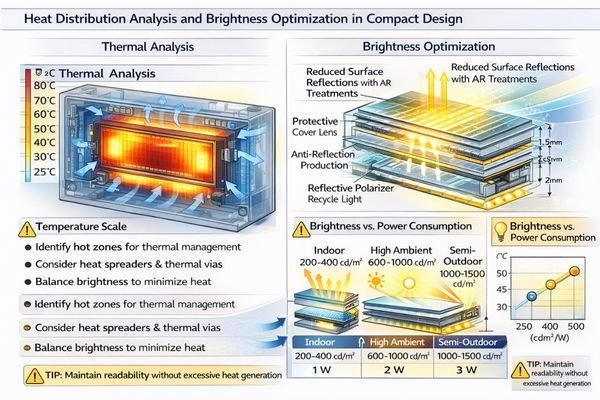
I evaluate whether the application requires true sunlight readability or high-ambient visibility, then match brightness targets with realistic thermal management4 and power budgets. In limited space, I treat “brightness” as a system outcome rather than a single number: the same backlight power can look very different depending on reflections, viewing angle, and the front window conditions. I confirm the typical viewing direction and mounting angle early so we don’t waste luminance into unused angles, and I align the brightness target with an operating temperature plan (including derating behavior when the enclosure heats up). Anti-reflection treatments and efficient optical stacks help achieve readability goals without excessive backlight power, and they often reduce the thermal burden more effectively than simply pushing LED current.
| Environment | Brightness Target | Thermal Considerations | Power Optimization |
|---|---|---|---|
| Indoor Control | 200-400 cd/m² | Standard heat dissipation | Efficient dimming control |
| High Ambient | 600-1000 cd/m² | Enhanced thermal paths | Managed LED current |
| Semi-Outdoor | 1000-1500 cd/m² | Active cooling consideration | Temperature derating |
The balance requires matching environmental needs with realistic thermal and power constraints in compact designs, then validating that readability remains stable across temperature and aging rather than only at room-temperature demos.
What interface and signal-chain details matter most when routing space is tight?
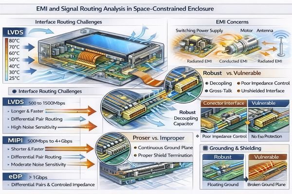
Constrained routing amplifies signal integrity, EMI, and ESD vulnerabilities requiring careful interface selection.
Tight routing proximity to switching circuits, motors, or antennas increases noise susceptibility. Critical factors include interface robustness relative to cable length, shielding feasibility, grounding strategy, impedance control, and ESD protection near front panel entry points.
Based on the projects I support with embedded controller teams, compact designs force sharp cable bends and dense routing near noise sources. To make interface decisions practical, I start with three checks: the required cable length between host and module, the presence of strong noise sources and return-path interruptions, and how reliably we can control grounding and shielding in the enclosure. I assess the complete signal chain from connector type through FPC length, shielding requirements, and grounding implementation to maintain stable display operation, and I verify timing margin assumptions early so the system does not become fragile to small layout changes. Backlight power requirements, dimming method compatibility, and inrush current behavior must align with system power architecture early in design. For complex routing validation or interface optimization guidance, technical teams can reach out to info@lcdmodulepro.com during integration planning.
Interface Selection for Short Routes
LVDS, eDP, and MIPI interfaces have different noise immunity and routing requirements5. In compact products, I treat interface selection as a risk-control choice: short, well-controlled routes may allow simpler routing and fewer mitigation layers, while longer or noisier paths benefit from differential signaling discipline, controlled return paths, and practical shielding. A common mistake is assuming that a short cable automatically guarantees stability—if the return path is broken by gaps, connectors, or chassis transitions, even short routes can be noisy. I therefore confirm that routing can maintain consistent impedance behavior, stable grounding, and robust ESD entry protection near the front panel before finalizing the interface plan.
Backlight Integration Considerations
Backlight power supply location, dimming control method, and LED driver placement affect both electrical performance and thermal management in compact designs. I validate backlight integration by checking the driver’s placement relative to the module, current loop area, grounding strategy, and PWM dimming behavior against EMI constraints. A practical criterion is whether the dimming method introduces visible artifacts (flicker, banding) under the intended camera or human viewing conditions, and whether inrush current can cause brownout or reset on the system rail. When space is tight, keeping the power path predictable and minimizing noisy loop areas often matters as much as the nominal power rating.
How to select the right LCD module type for compact products?
Module selection follows a constraint hierarchy prioritizing mechanical fit, optical requirements, and electrical integration.
I rank constraints in "must-not-break" priority: mechanical envelope first including active area positioning and FPC routing, optical needs including brightness and viewing requirements, electrical interface compatibility, integration risks including cover lens requirements, and lifecycle considerations including supply continuity.
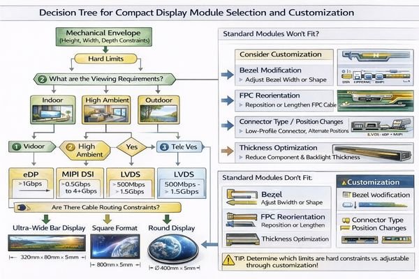
In my experience with space-critical applications, systematic constraint validation eliminates redesign loops and integration surprises. I keep selection disciplined by documenting the non-negotiables (Z-height, keep-out zones, FPC sweep area, connector access), then aligning optical targets with a thermal plan and confirming the interface can remain stable with the real routing constraints. When standard modules cannot meet mechanical restrictions, customization provides the most predictable path by optimizing bezel dimensions, thickness distribution, FPC orientation, and mounting features around specific enclosure requirements, rather than forcing compromises that appear late during EVT/DVT.
| Application / Scenario | Usage Pattern | Display Requirements | Recommended Model | Key Integration Considerations |
|---|---|---|---|---|
| Ultra-wide Control Interface | Horizontal status display | Extended aspect ratio, indoor brightness | BU215X | FPC exit direction, mounting point alignment |
| Round Instrument Display | Central gauge/meter | Circular active area, standard brightness | RD157H | Bezel integration, rotational mounting |
| Square Compact HMI | Touch control interface | Balanced dimensions, touch integration | SQ198H | Z-height optimization, touch stack clearance |
| Custom Form Factor | Non-standard opening | Optimized fit, specific constraints | Custom | Tailored mechanical envelope, FPC routing |
FAQ
In a tight enclosure, should I prioritize a thinner module or a narrower bezel?
I prioritize what the enclosure cannot accommodate: if Z-height is the hard limit, thickness wins; if the front opening is fixed and every millimeter of viewable area matters, bezel and active-area utilization win. We confirm the true mechanical keep-outs and tolerance stack-up before deciding.
What’s the most common mechanical mistake in limited space integration?
Underestimating the FPC bend radius and connector mating height. The CAD view may look fine, but real assembly needs bending space, strain relief, and tool access, which can easily cause interference or long-term fatigue failures.
How can I improve readability without raising backlight power too much?
I first reduce reflections and improve optical efficiency: optimize the front window, use appropriate anti-reflection treatments if feasible, and confirm viewing angle so you aren’t "throwing" brightness where no one looks. Efficient dimming control and thermal management also keep brightness stable over time.
Does a cover lens or touch layer make integration harder in limited space?
Yes, because it adds thickness, adhesive layers, and alignment constraints, and it can increase reflections. I treat it as part of the full stack-up from day one and define bonding, sealing, and rework strategy early to avoid late surprises.
What interface risks increase when the host board is far from the module?
Longer interconnects increase susceptibility to noise, timing margins, and EMI/ESD issues. I confirm cable length, grounding, shielding feasibility, and the host’s timing tolerance early, then match the interface approach and layout rules to reduce image artifacts and resets.
How do I avoid supply continuity and EOL surprises for compact products?
I recommend defining second-source strategy early, aligning on lifecycle expectations, and validating critical specs with clear acceptance criteria. For tight mechanical designs, keeping a controlled change process is essential because even small dimensional shifts can break compatibility.
Conclusion
Choosing an LCD display module for limited installation space requires disciplined constraint ranking and early validation of mechanical, thermal, and electrical integration requirements. From my experience with space-critical designs, success depends on confirming the complete mechanical stack-up, tolerance accumulation, and FPC routing constraints before committing to tooling decisions. The goal is eliminating redesign loops through systematic verification rather than hoping standard modules will fit.
MEIDAYINGNUO specializes in space-optimized LCD solutions including ultra-wide bar modules, compact square formats, round displays, and fully custom mechanical envelopes tailored to specific enclosure constraints. Our engineering team provides mechanical validation support, thermal analysis, and custom development capabilities to ensure reliable integration without compromising performance or forcing enclosure modifications. Connect with our team when you need optimized solutions for challenging space requirements.
✉️ info@lcdmodulepro.com
🌐 https://lcdmodulepro.com/
-
Exploring tolerance accumulation helps in grasping its impact on design accuracy and can prevent issues during the development phase. ↩
-
Exploring FPC bend radius requirements can help you design more reliable and efficient electronic assemblies. ↩
-
A well-structured mechanical checklist can streamline the design process and minimize redesign loops, enhancing efficiency. ↩
-
Exploring thermal management can reveal strategies to enhance display longevity and performance under varying conditions. ↩
-
This resource will provide insights into optimizing interface selection for better performance in compact designs. ↩