Circular and shaped custom LCD modules introduce manufacturing complexities that affect process stability, yield rates, and lead times due to non-standard geometries and specialized tooling requirements.
Shaped custom LCD modules carry elevated risk because perimeter operations dominate process capability instead of standard rectangular constraints. Success requires manufacturing-aware design margins, process-window validation, and disciplined change control to manage yield learning curves and tooling dependencies.
In my LCD display module integration work at MEIDAYINGNUO, I’ve observed that shaped modules1 fail most often from underestimating how geometry affects process stability and yield predictability. Teams focus on achieving the desired shape while overlooking how tight radii, narrow borders, and alignment sensitivity amplify normal manufacturing variation into visible defects. The practical cost shows up quickly: edge-related scrap that drives yield learning curves, subjective cosmetic debates that delay sign-off, and schedule slips when fixtures or inspection methods must be reworked. Successful shaped module projects require manufacturing-first design thinking that treats the perimeter as the primary risk zone.
Why do circular and shaped custom modules carry higher manufacturing risk?
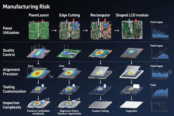
Shaped modules push beyond standard rectangular manufacturing processes, creating new risk vectors in tooling, alignment, and process control.
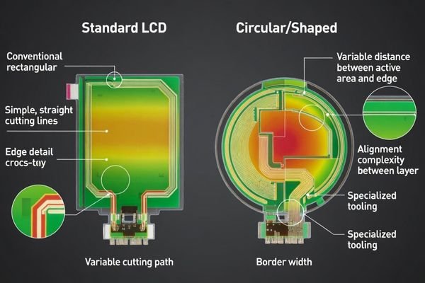
Circular and shaped modules increase risk because non-rectangular outlines reduce usable panel area, create edge-related stress concentration points, and amplify sensitivity to alignment drift between active area, bezel coverage, and final cut geometry. Supply chain standardization decreases as tooling, cutting methods, and inspection fixtures require customization.
From an engineering standpoint, I usually explain that shaped modules convert simple dimension control into process-window management across multiple interdependent steps. By “process window,” I mean the range of normal variation that still passes edge quality, alignment, and cosmetic acceptance—without relying on perfect handling or perfect alignment. Small deviations that would be invisible on rectangular modules become edge chips, light leakage, mask shift, or assembly scrap when shape margins are constrained. The perimeter becomes the dominant design constraint rather than the display center. As an early risk screen, I focus on three items that determine whether the project can be stable: the border/margin between the active area and cut edge (including the visible mask window), the edge-quality target and how it will be inspected, and the repeatability of the alignment and inspection fixtures that control the perimeter stack-up.
Geometric Complexity Factors
Non-rectangular geometries introduce stress concentration at corners2, variable edge-to-active-area distances, and alignment sensitivity between multiple layers. These factors reduce process margins and increase sensitivity to normal manufacturing variation. In practice, I validate the geometry by checking whether normal alignment drift could expose unwanted edges, clip the visible mask boundary, or make light leakage visible from the real viewing distance and angle. A common mistake is treating the shape outline as the main constraint and leaving the active-area-to-border relationship “for later,” which often turns into late cosmetic debates and rework because shaped edges reveal what rectangular bezels typically hide.
Tooling and Process Customization
Shaped modules require custom cutting dies, bonding fixtures, inspection gauges, and handling methods that lack the process maturity of standard rectangular tooling, introducing variability and learning curve delays. The most common tooling-related mistake is starting builds without defining what “good edge” means and how it will be measured, then discovering that different operators or fixtures produce different cosmetic outcomes. I prioritize early alignment fixture repeatability and inspection gauge repeatability because without consistent measurement, yield learning becomes guesswork and schedule becomes unpredictable.
Which process steps most affect yield for shaped modules?
Yield in shaped modules concentrates around perimeter operations that demand precision alignment and edge quality control.
Critical yield-affecting steps include outline forming and cutting operations, cover lens or decorative border alignment, bonding and adhesive thickness control, and any processes near the perimeter where stress concentration can initiate cracks, chips, or delamination. Process capability must be validated for edge quality and repeatability.
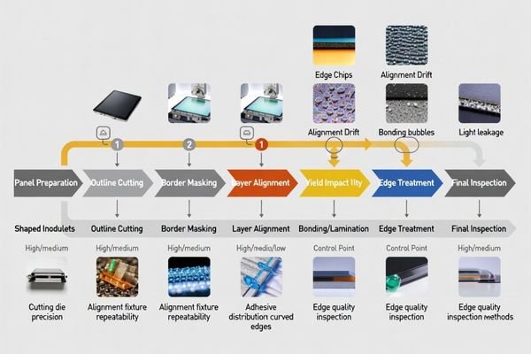
Based on the projects I support with custom shape requirements, yield losses concentrate at operations that combine mechanical stress with tight tolerance requirements. When geometry includes sharp radii, thin bridges, or narrow borders, the perimeter becomes the primary failure mode rather than center-area defects typical in rectangular modules. The yield-impact symptoms are usually very specific: edge chips or micro-cracks after cutting/handling, mask misalignment that exposes borders or creates an uneven ring, localized light leakage near curved edges, and bonding defects3 such as bubbles or delamination that are more visible near the perimeter. To make yield predictable, I recommend tying these symptoms to quantitative acceptance criteria and verifying process capability on the exact perimeter operations that create them—rather than assuming the rest of the module’s process maturity will carry over from rectangular builds.
How do design decisions influence process stability and scrap rate?
Design choices directly impact manufacturability by either supporting or constraining process windows and variation tolerance.
Process stability improves when designs respect manufacturable margins including adequate border width between active area and cut edge, realistic alignment tolerance between display and cover layers, and avoidance of stress-concentrating features like ultra-thin sections or sharp internal corners. The design must account for interconnect routing and mounting constraints.
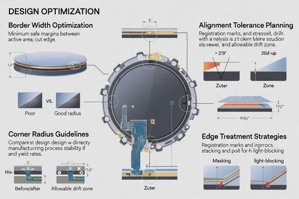
When I troubleshoot yield issues in shaped modules, most problems trace to insufficient manufacturing margin in the original design. Edge masking strategy, light-blocking approach, and backlight constraint near the perimeter require special attention because shaped edges reveal artifacts that rectangular bezels normally hide. I treat the design “pass/fail” as whether it can tolerate normal variation: border margin must still cover expected alignment drift, radii and corner features must be robust to handling and perimeter stress, and mounting/cable routing must avoid introducing bending or point loads near fragile edges. If stability depends on perfect execution, scrap rate will be the schedule driver.
| Design Element | Yield Impact | Stability Factors | Risk Mitigation |
|---|---|---|---|
| Border Width | High – affects stress concentration | Typical starting margin should cover expected alignment drift (Pending Confirmation) | Reserve margin and define visible mask window |
| Corner Radii | High – sharp corners concentrate stress | Larger radii generally improve edge robustness (Pending Confirmation) | Avoid stress concentration points |
| Alignment Tolerance | Critical – affects cosmetic appearance | Set tolerances based on fixture repeatability (Pending Confirmation) | Design for achievable precision |
| Edge Treatment | Medium – affects light leakage | Consistent masking and light-blocking strategy | Reduce edge artifacts and leakage visibility |
Manufacturing-aware design reduces yield risk4 by supporting process capability rather than constraining it, and the best designs define the visible window and edge requirements in a way that is measurable and repeatable.
What lead-time risks come from tooling, validation, and change control?
Lead time expansion results from custom tooling requirements, extended validation cycles, and change control complexity unique to shaped geometries.
Lead time increases because cutting dies, bonding jigs, inspection gauges, and packaging systems become project-specific rather than off-the-shelf. Validation requires additional iteration to establish edge quality and cosmetic acceptance criteria. Change control becomes critical because geometry modifications can trigger complete tooling rework.
I’ve found that shaped module schedules often underestimate the learning cycle required to achieve stable yield and cosmetic consistency. In most shaped projects, lead time is driven less by diagonal size and more by the dependency chain of tooling completion, validation iteration, and change-triggered rework. Early prototype phases must validate fixtures, cutting processes, and inspection methods before production tooling commitment. For comprehensive project planning and risk assessment support, engineering teams can contact info@lcdmodulepro.com during early development phases.
Tooling Dependencies
Custom tooling requirements include cutting dies for outline formation, alignment fixtures5 for bonding operations, inspection gauges for dimensional verification, and specialized packaging to protect delicate shaped edges during handling and transport. Tooling risk increases when edge quality and cosmetic measurement are not defined early, because the “right” fixtures and gauges depend on what you are trying to control and how you will accept or reject. The tooling items most likely to drag schedule are often those that must be iterated—alignment fixtures that must hit repeatability targets, inspection gauges that must match the visible window definition, and protective packaging that prevents edge damage from becoming hidden scrap.
Validation Complexity
Validation cycles extend because acceptance criteria for edge quality, alignment accuracy, and cosmetic appearance require iteration to establish realistic standards that balance quality with achievable process capability. I recommend defining the visible acceptance zone from the real viewing distance and angle first, then setting measurable limits for edge chips, mask alignment, and light leakage so sign-off is based on pass/fail rather than subjective opinions. When those criteria are frozen early—together with the viewable window and perimeter stack-up—validation becomes confirmation rather than discovery.
How to reduce risk and choose a shaped-module solution path?
Risk reduction requires systematic approach to design margins, process validation, and project management tailored to shaped module complexities.
I reduce shaped module risk by converting design intent into measurable manufacturing margins, mapping processes to risk zones with specific attention to perimeter operations, defining quantitative acceptance criteria for edge quality and cosmetics, and structuring project workflow around yield learning phases that validate manufacturability before production commitment.
In my experience with complex shaped modules, success depends more on manufacturing discipline than geometric ambition. Projects succeed when design margins support process capability, validation phases systematically reduce perimeter-related risks, and change control prevents late modifications that trigger tooling rework. A practical project approach is to organize the prototype workflow around perimeter risk burn-down: first validate cutting/edge quality and alignment repeatability (including the visible mask window), then validate bonding thickness windows and cosmetic standards under representative handling and thermal exposure, and only then move to production stability checks such as inspection gate repeatability and batch consistency.
To make this actionable, I typically align the solution path to a short review checklist that forces clarity on the biggest shaped-edge risks:
- Geometry margin check: Confirm the active-area-to-edge margin and visible border can cover expected alignment drift, and remove fragile features (thin bridges, sharp internal corners) that concentrate stress.
- Perimeter process plan: Identify the yield-critical perimeter steps (cutting, alignment, bonding) and define how each will be fixtured, handled, and inspected for repeatability.
- Cosmetic acceptance criteria: Define what is visible at the real viewing distance/angle, then set measurable limits for edge chips, mask shift, and light leakage to avoid subjective debates.
- Yield learning plan: Plan early builds specifically to close edge-quality and alignment repeatability risks before committing to production tooling.
- Change-control protection: Lock the viewable window and mechanical interfaces early, and require impact review for any change affecting cut edge, border/mask, or the alignment stack-up to prevent tooling rework and re-validation.
FAQ
Why is yield often lower for circular or shaped modules at the beginning?
Early yield is lower because fixtures, cutting quality, and alignment windows are still being tuned, and the perimeter is far more sensitive to small variation than a standard rectangular bezel-hidden design.
What geometry features most commonly drive scrap?
Tight radii, sharp internal corners, thin bridges, and very narrow borders near the cut edge tend to concentrate stress and reduce process capability, increasing chips, cracks, and cosmetic defects.
How can we define cosmetic acceptance criteria for shaped edges?
I recommend defining what is visible from the real viewing distance and angle, then setting measurable limits for edge chips, mask alignment, and light leakage so pass/fail doesn’t depend on subjective opinions.
What should be validated before committing to tooling?
I validate the edge-quality process capability, alignment repeatability between display and cover/mask, bonding thickness windows, and inspection fixture repeatability, because these are the main yield drivers.
Why does lead time increase even when the display size is small?
Shaped designs often require custom cutting, bonding jigs, inspection gauges, and additional validation loops, so schedule is driven by tooling and iteration rather than by diagonal size.
When should we consider a design change to improve yield?
If early builds show repeated edge-related scrap, I consider increasing border margin, relaxing radius constraints, or adjusting the mask strategy so the process window can tolerate normal variation.
How do you protect the project from late geometry changes?
I lock the viewable window and mechanical interfaces early, enforce revision control across drawings and samples, and require impact review before any change that affects the cut edge, border, or alignment stack-up.
Conclusion
Circular and shaped custom LCD modules require manufacturing-focused risk management because perimeter operations dominate process capability and yield outcomes. Success depends on designing with adequate manufacturing margins, validating process windows through systematic prototype phases, and maintaining disciplined change control to prevent tooling rework. The key is treating geometric complexity as an engineering constraint rather than just an aesthetic choice, using a repeatable logic that is easy to apply: perimeter risk first, yield driven by edge quality and alignment repeatability, and lead time driven by tooling dependencies, validation iteration, and change-triggered rework.
MEIDAYINGNUO specializes in shaped custom LCD module development with comprehensive manufacturing risk assessment, process optimization, and yield management support. Our engineering team provides design consultation focused on manufacturability, systematic validation planning, and production transition management for complex geometries. Contact our custom development team when shaped module projects require manufacturing-aware design optimization and risk mitigation strategies.
✉️ info@lcdmodulepro.com
🌐 https://lcdmodulepro.com/
-
Understanding the challenges of shaped modules can help improve design and manufacturing processes, leading to better yield and stability. ↩
-
Understanding stress concentration at corners is crucial for improving design and manufacturing processes, ensuring better product durability. ↩
-
Exploring bonding defects prevention techniques can enhance product quality and reliability, crucial for successful manufacturing. ↩
-
Exploring strategies to minimize yield risk can enhance your design process, leading to improved stability and reduced scrap rates. ↩
-
Understanding alignment fixtures is crucial for ensuring precision in manufacturing processes, enhancing product quality and efficiency. ↩