Designing custom industrial LCD display modules requires systematic integration of size optimization, brightness sustainability, interface robustness, and mechanical validation to achieve reliable field performance.
Custom industrial LCD module success depends on constraint-driven design that balances viewing task requirements with thermal limits, interface stability, and mechanical integration reality. The approach prioritizes real-world operating conditions over nominal specifications to prevent redesign cycles and field failures.
In my LCD display module integration work at MEIDAYINGNUO, I’ve learned that custom industrial modules1 fail most often from misaligned priorities during specification. Teams focus on maximizing screen area or brightness numbers while underestimating thermal constraints, mechanical integration complexity, or interface stability under real routing conditions. A disciplined approach treats customization as an engineering validation exercise that links every specification choice to measurable integration and reliability outcomes. To start efficiently, I typically ask for the front opening and real viewable window definition, maximum Z-height and tolerance stack, mounting constraints and datum strategy, FPC routing space and service access requirements, host interface and timing expectations, the operating environment (temperature, ambient light, duty cycle), and whether a cover lens or touch layer is required.
How do you define the right display size when space and usability conflict?
Effective size definition starts from viewing task requirements rather than maximum available enclosure space.
I define optimal size by confirming minimum legible character dimensions, typical viewing distance, and operator approach angles, then mapping these to active area requirements that support the UI without forcing excessive brightness or compromised font readability. The sizing process accounts for bezel requirements, alignment tolerances, and cover lens borders.
Based on the projects I support with industrial equipment developers, I work backward from the true viewable window after accounting for mechanical tolerances and assembly drift. I treat size as “pass/fail” against the real task: the smallest critical text and icons must remain legible at the worst viewing distance and angle that operators actually use, and the UI must remain readable without forcing a brightness level the enclosure cannot sustain thermally. The optimal size preserves operator interaction comfort while fitting within keep-out zones for mounting, FPC routing, and service access. In industrial products, assembly robustness and service accessibility often matter as much as screen area optimization, because a design that is barely compatible on paper tends to become fragile in production and difficult to service in the field.
Viewing Task Analysis
Character legibility depends on viewing distance, ambient lighting, and operator position. I confirm the smallest critical text size2 and information density requirements, then validate that the chosen resolution and physical size maintain readability under worst-case conditions. In practice, I start from the most demanding UI element (the smallest label that must never be misread) and verify it against the real viewing geometry, including off-axis viewing and glare sources that reduce contrast. If readability only works when the backlight is pushed beyond a sustainable level, I treat that as a sizing issue rather than a brightness “upgrade,” because it usually creates a thermal and lifetime penalty that shows up later as dimming, color shift, or reduced stability over long duty cycles.
Mechanical Envelope Constraints
Real usable area differs from nominal cutout dimensions due to bezel overlap, mounting tolerances, and cover lens borders. I reserve assembly margin so that normal production variation doesn’t clip displayed content or expose unwanted edges. A common failure mode is designing to the nominal cutout and discovering during build that bezel overlap or cover lens borders encroach on content, especially after normal alignment drift. My pass/fail check is simple: after worst-case assembly shift, the active content remains fully visible, borders remain cosmetically acceptable, and the design still preserves connector reachability and cable routing space for service and rework rather than only for a one-time assembly.
What brightness target should you choose for industrial environments?
Brightness selection requires balancing ambient light requirements with thermal sustainability and backlight lifecycle considerations.
I classify environments into controlled indoor lighting, high-ambient indoor near windows, and direct outdoor exposure, because each category changes power requirements, thermal design complexity, and backlight aging patterns. Brightness targets must account for thermal constraints and long-term stability requirements.
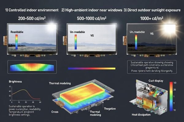
From an engineering standpoint, I usually treat luminance as a lifecycle requirement rather than a peak specification. Industrial enclosures limit heat removal capability, and high LED current accelerates backlight degradation, so I align the brightness target with what the thermal path can sustain after the enclosure reaches thermal steady state, not only at room-temperature demos. I also consider front optics including cover lens reflections and surface treatments, because improving optical efficiency3 often achieves better usability than simply increasing LED drive current. The practical acceptance criterion is that readability remains stable at the target ambient light after warm-up and across expected temperature ranges, with predictable derating behavior rather than sudden drops or unstable flicker under thermal stress.
| Environment Type | Brightness Range | Thermal Considerations | Design Priorities |
|---|---|---|---|
| Controlled Indoor | 200-500 cd/m² | Standard thermal design | Efficiency optimization |
| High Ambient Indoor | 500-1000 cd/m² | Enhanced heat dissipation | Optical stack optimization |
| Outdoor/Direct Sun | 1000+ cd/m² | Active thermal management | Sustainable power design |
The optimal brightness target represents the lowest luminance that maintains readability across actual ambient conditions with adequate thermal margin, including steady-state conditions and expected aging over the product’s duty cycle.
Which interface is best for your host system and signal routing limits?
Interface selection must match host controller capabilities, routing path constraints, and electromagnetic environment realities.
I select interfaces by evaluating three critical factors: host controller native support capabilities, interconnect path length and noise environment, and achievable grounding and shielding implementation in the target enclosure. The optimal interface maintains timing margins and EMI immunity under actual routing conditions.
When I troubleshoot field issues on products integrating LCD display modules, I often find that interface problems stem from inadequate attention to routing realities. Compact industrial designs force cable routing near switching supplies, motors, or wireless circuits, creating noise coupling and ground loop issues. I start by ranking interface risk from the real cable length, the return-path continuity you can realistically maintain, and proximity to noise sources, then choose an interface and layout discipline that preserves timing margin under those constraints. The best interface choice provides adequate noise immunity and timing margin for the actual mechanical and electrical environment, and I validate it with the real harness geometry rather than a simplified bench setup. For complex interface validation or signal integrity analysis support, teams can reach out to info@lcdmodulepro.com during development planning.
Signal Chain Validation
Complete signal integrity requires validating connector choice, FPC length and bend characteristics, return path continuity, and ESD entry points near the front panel. I confirm that grounding strategy and shielding implementation support stable operation under vibration and temperature cycling. Practically, I review how the connector is retained, whether the FPC routing creates an unintended strain point, and whether the return path is continuous across connectors and chassis transitions. My acceptance criteria are based on stability outcomes: no intermittent artifacts, no unexplained resets, and no sensitivity spikes when the cable is moved within the allowed routing envelope, because marginal designs often “work” until vibration or assembly variation makes the weakness repeatable.
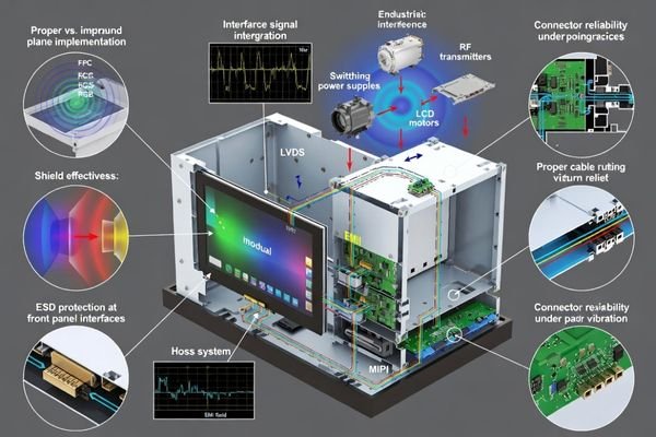
EMI and Noise Immunity
Industrial environments often contain significant electromagnetic interference from motor drives, welding equipment, and power conversion circuits. Interface selection must account for differential signaling requirements, common-mode rejection, and grounding architecture to maintain display stability. I treat EMI planning4 as a front-loaded architectural decision: if the routing environment is noisy, I prioritize a grounding and return-path strategy that is robust to assembly variation, then use shielding as reinforcement rather than a last-minute patch. A common mistake is assuming the shortest route is automatically safe; if the return path is broken or reference planes change unpredictably, even short interconnects can be noisy. I therefore verify that the electrical architecture remains stable under realistic cable placement and that ESD entry points near the front panel are explicitly managed rather than left to chance.
How do you engineer mechanical integration to avoid late redesigns?
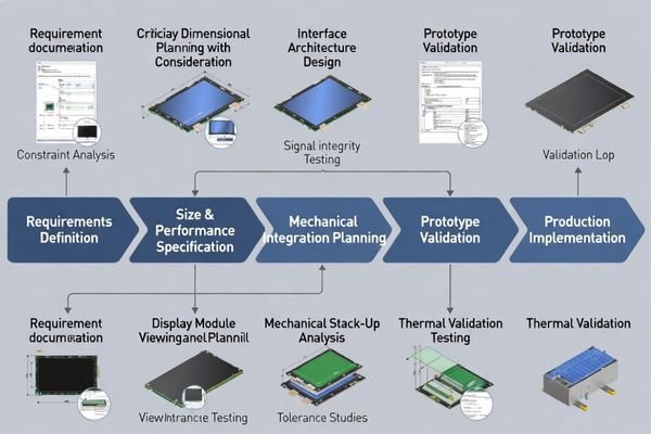
Successful mechanical integration requires early verification of the complete stack-up and clear definition of keep-out constraints.
I establish mechanical integration around verified stack-up analysis and specific keep-out rules including maximum Z-height with tolerance and compression effects, front window alignment considering assembly drift, mounting datum strategy, and cable routing envelope that respects bend radius and service access requirements.
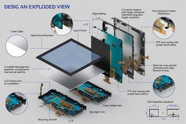
I pay particular attention to local thickness variations at backlight edges and connector regions, because these areas commonly cause interference during production even when nominal dimensions appear acceptable in CAD. I also verify the practical assembly and rework path—tool clearance, connector reachability, and the ability to replace the module without damaging seals or cables—because tight designs often fail in manufacturing not from “fit,” but from not being buildable repeatedly. When cover lens or touch integration is required, I treat bonding, sealing, and rework as primary design constraints since adhesive thickness variation and assembly stress can introduce warpage, light leakage, or optical artifacts. The mechanical goal is to convert “it should fit” into repeatable pass/fail criteria that can be checked before tooling and confirmed during EVT/DVT.
Stack-Up and Tolerance Management
Mechanical success requires accounting for cumulative tolerance effects across all layers from front cover through LCD module to final mounting surface. I validate clearance under worst-case tolerance combinations and thermal expansion conditions. In practice, I build a cross-section stack-up with tolerance windows and identify the local thickness peaks rather than relying on average thickness. The common mistake is designing to nominal and discovering that gasket compression, adhesive thickness spread, or bracket variation consumes the last margin, so I reserve realistic assembly clearance and ensure the module seating datum is stable and repeatable.
Integration Validation Strategy
Effective validation confirms assembly feasibility, alignment accuracy, and interconnect strain relief before tooling commitment. This prevents basic fit problems and ensures that mechanical integration supports long-term reliability under vibration and thermal cycling. My validation sequence5 usually starts with buildability checks (seating, fastening, connector mating, cable sweep) followed by functional stability under expected stress, because passing a performance test once is not meaningful if the design cannot be assembled consistently. The pass/fail criteria focus on repeatability: consistent alignment in multiple builds, no cable pinching or rubbing in the allowed envelope, and stable operation after the mechanical stress that the product will actually see.
How to choose a custom industrial LCD display module partner and configuration?
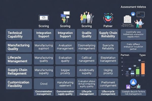
Partner and configuration selection requires systematic evaluation of technical capability, integration support, and lifecycle management.
I use a constraint-first approach that evaluates every specification choice against integration risk and lifecycle stability. This includes application analysis, size optimization around real viewing windows, sustainable brightness targets, interface stability validation, and comprehensive mechanical integration planning.
In my experience with custom industrial products integrating LCD display modules6, successful partnerships depend on engineering depth rather than just manufacturing capability. I look for a partner who can translate requirements into measurable rules: a viewable-window definition with alignment allowances, a sustainable brightness target tied to a thermal plan, an interface plan that remains stable with real routing constraints, and a mechanical integration package that defines keep-out zones, mounting datums, and strain relief intent. I also prioritize lifecycle behaviors—change control, documentation quality, and supply continuity—because custom modules often live in industrial products far longer than consumer timelines. The most effective way to reduce integration risk is aligning early on the engineering deliverables and the validation plan that proves those deliverables survive real operating conditions.
Because this is a fully custom recommendation, I avoid forcing a generic “model selection table” that can mislead integration decisions. Instead, I recommend anchoring configuration choices to a short set of decisions that drive cost, risk, and schedule: confirm the viewable window and UI readability target, lock the sustainable brightness requirement with a thermal margin and derating rule, choose an interface based on real cable length and grounding feasibility, and freeze a mechanical stack-up with worst-case tolerance clearance and service access. From there, I align the module configuration around the enclosure realities—FPC exit direction and strain relief, connector retention strategy, cover lens or touch integration approach, and EMI/ESD entry-point handling—then validate the complete system with a buildable prototype and a test plan that reflects real operating conditions rather than ideal bench setups.
FAQ
What information do you need first to start a custom LCD module design?
I typically need the enclosure drawing with the front opening, maximum Z-height, mounting constraints, FPC routing space, the host interface and timing expectations, the target environment (temperature and ambient light), and whether a cover lens or touch layer is required, so we can define a realistic stack-up and integration rules from day one.
How do I avoid choosing a size that looks good in CAD but fails in production?
I verify the real viewable window including tolerances, bezel overlap, and any cover lens border, then reserve assembly margin so small shifts do not clip content or expose edges. I also confirm connector access and FPC bend space with a physical routing envelope, not only nominal dimensions.
How should I set brightness if the product runs 24/7?
I set the brightness target based on the worst ambient light that matters, then confirm the thermal path and derating behavior so the module can sustain that luminance without overheating or accelerating backlight aging. Dimming strategy and optical efficiency often reduce the needed LED current while keeping readability stable.
What are the most common interface risks in industrial integration?
The most common risks are marginal timing due to uncontrolled routing, noise coupling from power converters or motors, weak grounding/return paths, and insufficient ESD protection near the front panel. Mechanical micro-motion at connectors can also create intermittent issues that look like "signal" problems.
Do I need a cover lens, and how does it change the design?
If the front panel needs impact resistance, sealing, or chemical durability, a cover lens can be important, but it adds thickness and alignment constraints. I treat it as part of the stack-up early, defining bonding, stress control, light-blocking, and rework strategy to avoid warpage and optical artifacts.
How do you manage lifecycle risk for a custom module?
I recommend defining change control and second-source strategy early, documenting critical mechanical and electrical acceptance criteria, and validating the design under representative stress so later component changes do not silently break fit or stability.
Conclusion
Choosing a custom industrial LCD display module requires disciplined engineering that integrates size optimization, brightness sustainability, interface robustness, and mechanical validation into one coherent system rather than treating these as independent decisions. Success depends on constraint-driven design that prioritizes real viewing requirements, thermal sustainability, and integration reliability over nominal specifications. As an engineer, I focus on reducing redesign risk by validating the complete system under representative operating conditions before committing to tooling, using a repeatable principle: define size from the viewing task and viewable window, set brightness from sustainable thermal margin, select the interface from real routing stability, and lock mechanical integration with worst-case stack-up validation and service access.
MEIDAYINGNUO specializes in custom industrial LCD display module development with comprehensive engineering support for size optimization, brightness analysis, interface validation, and mechanical integration. Our team provides design consultation, prototype development, and manufacturing support to ensure custom solutions meet industrial reliability and lifecycle requirements. Connect with our engineering team when developing tailored display solutions for demanding industrial applications.
✉️ info@lcdmodulepro.com
🌐 https://lcdmodulepro.com/
-
Understanding the challenges of custom industrial modules can help improve your integration process and avoid common pitfalls. ↩
-
Understanding the smallest critical text size is essential for ensuring that all UI elements are legible under various conditions. ↩
-
Exploring optical efficiency can lead to innovative solutions that enhance usability and performance in your projects. ↩
-
Effective EMI planning is essential for maintaining device stability in noisy environments, making this resource invaluable. ↩
-
Exploring the validation sequence helps in grasping the importance of assembly feasibility and long-term reliability in design. ↩
-
Explore this link to understand effective strategies for integrating LCD display modules, ensuring optimal performance and reliability. ↩