Custom LCD module projects require comprehensive deliverables that define integration parameters, validate performance, and ensure production consistency through documented specifications and validation evidence.
Effective custom LCD module deliverables transform project requirements into measurable acceptance criteria through complete datasheets, tolerance-defined mechanical drawings, and validation reports that prove readiness under representative operating conditions. These documents enable predictable integration and repeatable production outcomes.
In my LCD display module integration work at MEIDAYINGNUO, I’ve learned that inadequate deliverables1 are the primary cause of late-stage integration failures and production inconsistencies. Teams often receive incomplete documentation that lacks tolerance definitions, measurement conditions, or validation evidence, leading to assumptions that break during assembly or mass production. Comprehensive deliverables function as the engineering contract that aligns requirements with design decisions, validation planning, incoming inspection, and change review—so the project can scale without surprise tooling rework, repeated debug cycles, or batch-to-batch drift.
What deliverables should you expect in a custom LCD module project?
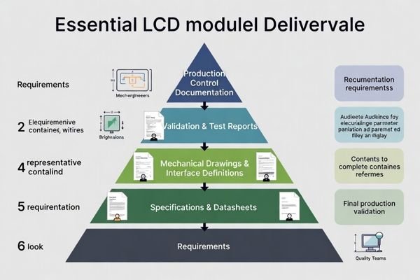
Complete deliverable packages establish the engineering foundation for successful integration and production scaling.
I define deliverables as the single source of truth that maintains alignment between requirements, integration design, and mass production control. The package must include datasheets capturing electrical, optical, and mechanical parameters with operating limits, mechanical drawings with tolerance definitions, and validation reports proving representative performance.
From an engineering standpoint, I usually treat deliverables as measurable acceptance criteria2 rather than reference materials. In a practical project, different teams rely on different parts of the package: mechanical teams need envelope, stack-up, and keep-out definitions to avoid interference; electrical and firmware teams need interface and power assumptions to avoid unstable behavior; test and quality teams need acceptance criteria and report evidence to sign off readiness; procurement needs version clarity, CTQ definitions, and change control so sourcing doesn’t quietly break compatibility. I also treat version consistency as a hard rule: drawings, datasheets, and reports must share the same revision identifiers, and each report must explicitly reference the exact revision tested, otherwise the evidence cannot be trusted for integration or production decisions.
Core Documentation Requirements
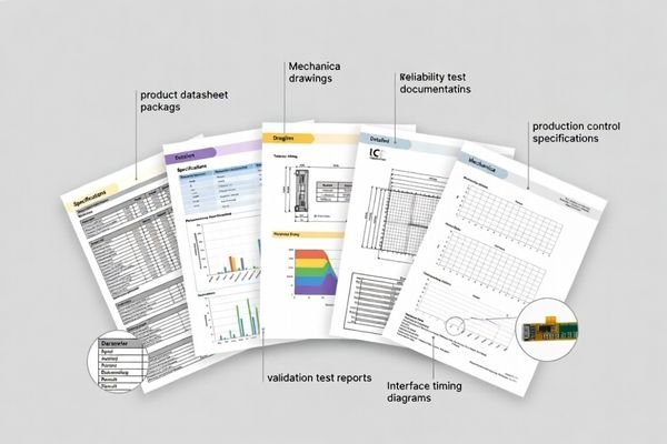
Essential deliverables include performance datasheets, mechanical envelope drawings, interface specifications, validation test reports, and production control documentation. Each document must include version control, measurement conditions, and clear acceptance criteria so teams can make build/no-build decisions without guessing. A deliverable package is only “complete” when it answers the questions that drive the highest-cost failures: will it fit with real tolerances, will it remain stable in the real signal and power environment, and can it be built repeatedly with consistent outcomes.
Version Control and Change Management
Effective deliverable management requires controlled version tracking, change impact documentation, and compatibility matrices to prevent configuration mismatches during production scaling and lifecycle management. The most common failure pattern I see is a subtle mismatch—drawings updated but test reports still reference an older configuration, or a datasheet parameter updated without documenting new measurement conditions—so I require a documented revision history and an impact note for any changes to CTQ parameters. The goal is simple: when anything changes, everyone knows what changed, why it changed, and what must be re-verified.
What should a custom LCD module datasheet include to avoid integration mistakes?
Effective datasheets prevent common integration failures through complete parameter definition and clear operating condition specifications.
A comprehensive datasheet prevents integration mistakes by clearly stating operating conditions, power rail and backlight driving requirements, interface timing specifications, optical performance under defined measurement conditions, and reliability considerations that affect lifecycle behavior. Critical parameters must distinguish guaranteed versus typical values.
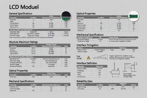
Based on the projects I support with system integrators, datasheet quality determines integration success more than individual specifications. Teams need clear operating limits, interface assumptions, and thermal constraints to make correct system design decisions. The datasheet must tie each performance claim to specific measurement conditions so comparisons remain valid. The three most common missing elements that create downstream failures are (1) incomplete measurement conditions (temperature, driving method, test pattern, stabilization time), (2) unclear interface assumptions3 (cable length expectations, termination/return-path constraints, grounding reference), and (3) backlight and dimming boundaries (control method limits, start-up behavior, derating expectations). For sign-off decisions, I treat “guaranteed” items as the boundaries acceptance criteria should enforce, while “typical” values guide design intent; when a parameter can break fit or stability, it should be defined with enforceable limits or a verified acceptance window rather than a single nominal number.
What mechanical drawings are essential, and what tolerances matter most?
Mechanical drawings must define the module as a buildable object within real enclosure constraints and assembly processes.
Essential drawings include outline dimensions with thickness distribution, mounting datums and hole patterns, keep-out zone definitions, connector and FPC location with routing constraints, and front window relationships including bezel overlap and viewable area positioning. Tolerances matter most where accumulation affects assembly or cosmetic appearance.
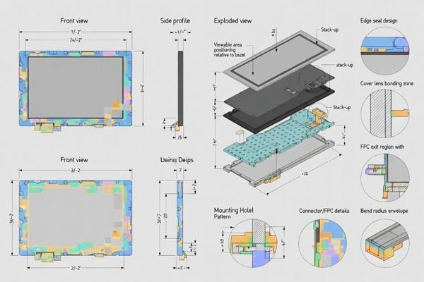
When I troubleshoot mechanical integration issues, most problems trace to missing tolerance information or incomplete keep-out zone definition. Z-height stack-up tolerance4, connector mating height variation, local thickness peaks at backlight edges, and active area alignment relative to the front opening represent the highest-risk tolerance zones that require explicit control. At minimum, a usable drawing package should include an outline/envelope drawing with datums, an installation or mounting drawing, an interface/connector and FPC location drawing (with routing envelope intent), a viewable-area definition relative to bezel and front opening, a keep-out drawing that reserves service/tool access, and a stack-up cross-section for any front stack integration such as cover lens or touch. My priority logic is to lock tolerances where failure is binary—won’t assemble, can’t mate connectors, clips content, exposes edges, crushes components—before spending effort on low-impact cosmetic dimensions.
| Drawing Type | Critical Information | Tolerance Priority | Integration Impact |
|---|---|---|---|
| Outline Drawing | External envelope, mounting points | Z-height stack-up, connector clearance | Assembly interference |
| Stack-up Cross-section | Layer thicknesses, adhesive zones | Cumulative thickness, alignment drift | Cover lens bonding, stress |
| Interface Drawing | Connector position, FPC routing | Mating height, bend radius | Service access, reliability |
| Viewable Area Definition | Active area to bezel relationship | Alignment tolerance, overlap | Content clipping, cosmetics |
Tolerance control focuses on parameters that directly affect assembly success and long-term reliability, and the drawings should make those control zones unambiguous rather than implied.
Which reports prove readiness: validation, reliability, and production control?
Validation reports transform custom modules from prototypes into production-ready solutions through documented performance verification.
Reports provide verification evidence tied to specific acceptance criteria including functional stability across temperature ranges, brightness performance under realistic conditions, interface stability under expected EMI/ESD exposure, and mechanical integrity after assembly stress. Production control documentation ensures batch consistency.
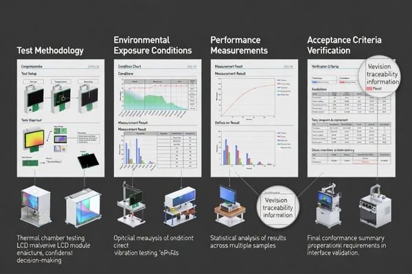
I evaluate reports based on their ability to predict field performance rather than just laboratory compliance. For industrial applications, this includes backlight aging expectations, seal or adhesive long-term behavior, and connector robustness under service access cycles. Production control evidence matters as much as performance validation because batch consistency depends on controlling manufacturing variation. A report is most useful when it is reproducible: it clearly states the tested configuration and revision, the test setup and connection method, the driving and dimming parameters, the environmental conditions and stabilization time, the acceptance criteria used, and any deviations or failures observed. Without that traceability, even “good results” don’t protect a project from later surprises. For comprehensive validation planning and report review support, engineering teams can contact info@lcdmodulepro.com during deliverable evaluation.
Performance Validation Evidence
Validation reports must cover thermal performance5 across operating temperature ranges, optical stability including brightness uniformity and color consistency, electrical performance under interface timing and noise conditions, and mechanical integrity after handling and vibration exposure. I also check that validation includes the transition behaviors that often cause field issues—warm-up, cool-down, and temperature changes—so stability is proven under the same patterns the product will actually experience.
Production Control Documentation
Production readiness requires documented critical-to-quality parameters, defined inspection methods, supplier control procedures, and change control processes that maintain consistency across production batches and component substitutions. I treat production control as part of the deliverables: CTQ definitions that lock the parameters that must not drift, inspection gates that confirm those CTQs, and a change-control process that triggers impact review and re-validation when a CTQ-relevant change is proposed.
How to review deliverables and choose a module solution with confidence?
Deliverable review follows the same priority order as potential failure modes to ensure comprehensive risk evaluation.
I review deliverables by evaluating mechanical fit and serviceability first, then optical and thermal sustainability, followed by interface robustness, and finally production readiness indicators. Document consistency and version matching prevent configuration mismatches that cause late-stage surprises.
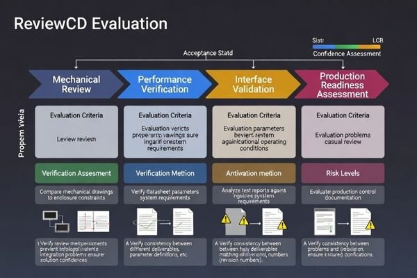
In my experience with custom module evaluation, deliverable quality predicts project success better than individual performance specifications. Complete documentation enables confident integration decisions while incomplete deliverables create hidden risks that emerge during production scaling. I also treat this review as a sequence of evidence checks: first confirm the mechanical drawings and stack-ups match the enclosure constraints and that tolerances leave real assembly margin, then confirm the datasheet’s measurement conditions and operating limits support the intended duty cycle, then confirm interface assumptions are realistic for routing and grounding, and finally confirm the reports validate the exact revision and configuration being proposed. If any document disagrees with another (for example, a drawing revision doesn’t match the tested revision in the report), I assume risk is open until the mismatch is resolved.
| Deliverable Category | Review Focus | Confidence Indicators | Risk Mitigation |
|---|---|---|---|
| Mechanical Documentation | Stack-up, tolerances, keep-outs | Complete envelope definition | Assembly interference prevention |
| Performance Datasheet | Operating limits, measurement conditions | Guaranteed vs. typical distinction | System design accuracy |
| Validation Reports | Test conditions, acceptance criteria | Representative stress testing | Field performance prediction |
| Production Control | CTQ parameters, change control | Batch consistency methods | Long-term reliability |
Systematic review ensures deliverables support both immediate integration and long-term production success, and it helps teams focus time on the documents that eliminate the most expensive late-stage surprises.
FAQ
What’s the difference between "typical" and "guaranteed" values in a datasheet?
I treat "typical" as guidance for design intent and "guaranteed" as what acceptance criteria should enforce. For critical parameters, I look for test conditions and limits that define pass/fail, not just nominal targets.
Which single drawing causes the most integration issues when it’s missing?
The stack-up cross-section with tolerances and keep-out zones. Without it, teams often discover Z-height conflicts, connector interference, or adhesive thickness drift only after builds.
What should be included to define the viewable area correctly?
I look for the relationship between active area, bezel overlap, and the front opening, plus an allowable alignment drift. This prevents content clipping and cosmetic edge exposure in production.
How do you confirm the report matches the actual configuration we will build?
I verify part numbers or revision identifiers, check that measurement conditions match the defined acceptance criteria, and ensure the tested sample includes the same optics, interface, and mechanical stack-up as the intended build.
What is CTQ and why does it matter for deliverables?
CTQ means "critical to quality." I use it to lock the parameters that must not drift—like key dimensions, interface behavior, or optical targets—so production remains consistent and changes trigger impact review.
If we only have limited time, which deliverables should we prioritize first?
I prioritize the mechanical drawing package with tolerances and keep-outs, then the interface/timing references, then a short validation summary tied to acceptance criteria. These reduce the highest-risk late surprises.
Conclusion
Comprehensive deliverables transform custom LCD module projects from concept discussions into predictable integration outcomes through complete documentation, validated performance evidence, and production control systems. Quality deliverables define measurable acceptance criteria, prevent version mismatches, and maintain consistency across production lifecycles. As an engineer, I rely on thorough documentation to align design decisions with validation evidence and ensure production readiness, using a repeatable deliverables principle: the datasheet defines parameters and measurement conditions, the drawings lock the mechanical envelope and tolerances, and the reports provide traceable evidence for the exact revision being built—supported by CTQ and change control to protect batch consistency over time.
MEIDAYINGNUO provides complete custom LCD module deliverable packages including detailed datasheets, tolerance-controlled mechanical drawings, comprehensive validation reports, and production control documentation. Our engineering team ensures deliverable quality supports confident integration decisions and reliable production scaling. Contact our documentation team when developing custom display solutions that require comprehensive engineering deliverables and validation evidence.
✉️ info@lcdmodulepro.com
🌐 https://lcdmodulepro.com/
-
Understanding the effects of inadequate deliverables can help prevent integration failures and ensure smoother project execution. ↩
-
Understanding acceptance criteria is crucial for ensuring project deliverables meet expectations and quality standards. ↩
-
Exploring interface assumptions can help teams make informed design choices and prevent integration issues. ↩
-
Understanding Z-height stack-up tolerance is crucial for ensuring proper assembly and avoiding costly errors in mechanical integration. ↩
-
Understanding thermal performance is crucial for ensuring product reliability and longevity under varying temperature conditions. ↩