Custom LCD module projects succeed through systematic workflow management that converts requirements into testable specifications, reduces risks through targeted prototyping, and validates mass production readiness.
Custom LCD module workflow success depends on early constraint definition, systematic risk reduction through prototype phases, and validation of repeatability before tooling commitment. The approach prioritizes engineering discipline over schedule compression to prevent expensive redesign cycles.
In my LCD display module integration work at MEIDAYINGNUO, I’ve learned that custom module projects fail most often from inadequate requirements definition or uncontrolled scope changes during development. Teams rush to prototyping without establishing clear acceptance criteria or change control processes, leading to repeated iteration cycles that consume schedule and budget. A disciplined workflow treats custom development as an engineering validation exercise with defined checkpoints and risk mitigation gates. To start efficiently, I typically request a compact “project input package1” that includes mechanical documents (front opening and target viewable window, maximum Z-height, datums/keep-out zones, tolerance stack and service access), electrical documents (host interface expectations, estimated cable length, power and dimming control, EMI/ESD constraints), and environment documents (temperature range, ambient light, duty cycle, vibration/shock, dust/moisture exposure). Clear inputs turn early discussions into verifiable specifications and prevent late surprises that drive tooling rework, validation delays, and field-return risk.
What inputs should you prepare to start a custom LCD module project?
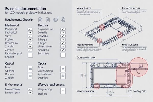
Effective project initiation requires engineering-ready inputs that prevent downstream rework and scope confusion.
I require clear definition of the viewable window and enclosure constraints including front opening dimensions, maximum Z-height limitations, mounting datums and keep-out zones, service access requirements, and operating environment specifications including temperature range, ambient light conditions, duty cycle patterns, and mechanical exposure.
From an engineering standpoint, I usually translate customer "wants" into measurable constraints that can guide design decisions. This includes confirming product-level priorities such as readability targets, lifetime expectations, and change control tolerance, because these drive optical stack choices, thermal margin requirements, and validation scope. I treat the requirement set as “engineering-ready” only when it can produce a cross-section stack-up, a routing envelope, and a preliminary acceptance criteria list; otherwise, teams tend to prototype quickly and then iterate repeatedly when basic assumptions change. When inputs are engineering-ready, the project moves from concept discussions to verifiable specifications.
Mechanical Constraint Definition
Complete mechanical inputs include enclosure cross-sections, tolerance stack-up analysis2, mounting strategy, FPC routing space, connector access requirements, and any cover lens or touch integration needs. I confirm assembly sequences and service accessibility early to avoid late-stage conflicts. In practice, I ask for the seating datum definition, the worst-case stack-up in Z (including compression or adhesive thickness windows), and the tool access path for connector mating and rework. Common late-stage failures come from “it fits once” designs—where local thickness peaks, missing tool clearance, or a tight cable sweep area make assembly non-repeatable and fragile under normal production variation.
Environmental and Performance Requirements
Operating environment definition covers temperature extremes, ambient lighting conditions, vibration and shock exposure, moisture and contamination risks, and duty cycle patterns. Performance requirements include brightness targets, viewing angle needs, and interface timing expectations. I also make sure requirements cover transitions, not only steady-state points, because field issues often happen during cold starts, warm-up, cool-down, and humidity/temperature crossings. A usable requirement statement enables validation planning: it tells me what to test, under what combined conditions, and what “pass/fail” should look like for readability, stability, and reliability.
How do you convert requirements into a feasible module concept and specification?
Requirements conversion follows a constraint hierarchy approach that ensures all specifications are measurable and testable.
I establish the constraint hierarchy by locking mechanical stack-up with worst-case tolerances, setting sustainable brightness targets that match thermal capabilities, and selecting interface approaches that remain stable under actual routing conditions. Each requirement maps to measurable specifications with clear acceptance criteria.
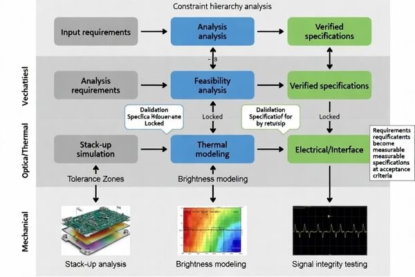
Based on the projects I support with industrial equipment developers, successful conversion requires defining measurable success criteria3 early. This means confirming that displayed content won’t clip after assembly drift, validating stable operation under expected EMI/ESD exposure, and ensuring predictable behavior across temperature transitions. I treat “testable specifications” as specific items that can be verified in builds and in stress checks: a defined viewable window and allowable alignment drift, a brightness target that remains readable after thermal steady-state and expected aging behavior, interface stability at the real cable length and grounding constraints, and a mechanical integration plan that preserves service access and strain relief. The specification becomes a testable document rather than a wish list, and it also becomes the basis for impact review when changes inevitably appear.
How do prototype phases reduce risk before committing to tooling?
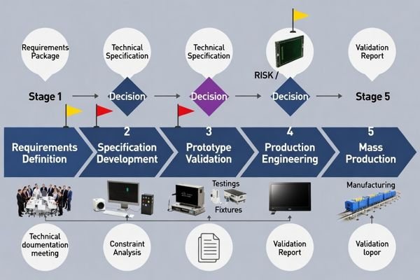
Prototype phases function as systematic risk-reduction checkpoints with specific learning objectives rather than general sample validation.
Early prototypes validate mechanical integration reality including stack-up clearance, connector accessibility, cable routing feasibility, and cover lens or touch bonding behavior. Subsequent phases validate performance stability under representative stress conditions and confirm process repeatability.
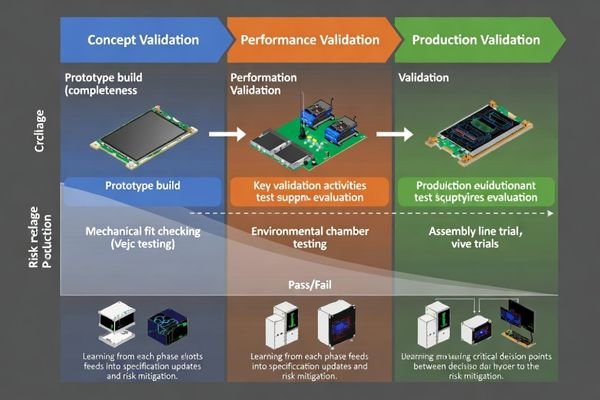
When I troubleshoot late-stage integration issues, most problems trace to mechanical conflicts4 that weren’t validated in early prototypes. Prototype phases should close specific risks and update specifications based on learning, ensuring tooling decisions are made with validated understanding rather than assumptions. I treat each phase as a gate with defined outputs: what we learned, what risks we closed, what acceptance criteria were confirmed or updated, and what remains open before moving forward.
| Prototype Phase | Primary Objectives | Validation Focus | Decision Points |
|---|---|---|---|
| Concept Validation | Mechanical fit, basic function | Stack-up clearance, connector access | Proceed to detailed design |
| Performance Validation | Thermal, optical, electrical stability | Stress testing, EMI screening | Interface and thermal confirmation |
| Production Validation | Process repeatability | Tolerance sensitivity, assembly variation | Tooling and fixture commitment |
Systematic prototype planning ensures each phase adds validated knowledge to support production decisions. I also make sure each phase ends with updated documentation—revised stack-up, routing envelope, and acceptance criteria—so the next build is not repeating the same uncertainty with a new sample. For comprehensive prototype planning and validation support, engineering teams can contact info@lcdmodulepro.com during project development.
What validation and change control are essential for mass production readiness?
Mass production readiness requires verifying process repeatability and establishing controlled change management systems.
Production readiness validation focuses on tolerance sensitivity, assembly process windows, performance stability across batches, and parameter drift monitoring. Change control systems prevent silent substitutions that could affect optical, mechanical, or electrical behavior.
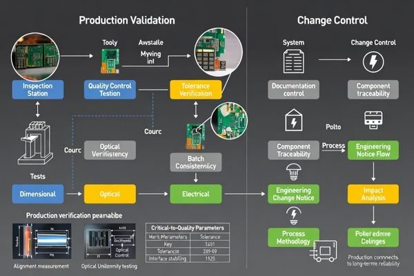
I focus on process windows rather than single-point performance because mass production success depends on consistent results across normal variation. This includes confirming that tolerance accumulation doesn’t affect viewable windows, validating interface stability across cable variation, and ensuring brightness uniformity remains within targets after thermal cycling. Critical-to-quality parameters must be locked with defined inspection gates and supplier controls. For me, mass production readiness is proven when multiple builds across normal variation consistently meet the same acceptance criteria—not when a single “golden sample” performs well.
Process Validation Requirements
Production validation confirms that assembly methods, tolerance variation, and material substitutions don’t introduce stress points, electrical instability, or optical artifacts. I establish acceptance criteria for incoming components, in-process checks, and final validation to maintain consistency. Practically, this means defining what needs to be measured every batch (CTQ dimensions and settings), where the inspection gates sit, and how process drift is detected before it becomes field drift. The pass/fail mindset is repeatability: consistent alignment and viewable window, stable interface behavior under normal cable variation, and predictable optical performance after thermal soak and representative cycling.
Change Control Implementation
Effective change control5 prevents component substitutions, process modifications, or specification drift from silently affecting product performance. Documentation systems track critical parameters and require impact analysis before any modifications to proven designs. I define CTQ items that must trigger impact review—mechanical stack-up contributors, interconnect/connector elements, backlight and dimming behaviors, and key optical and bonding materials—because these are the changes most likely to break fit or stability. The goal is to keep evolution controlled: changes happen, but they happen with traceability and re-validation scope that matches the risk.
How to choose the right module configuration and supplier support for your workflow?
Configuration and supplier selection prioritize integration risk management and lifecycle stability over individual specifications.
I select module configurations around mechanical integration margin, sustainable brightness targets with thermal headroom, and interface stability under actual routing conditions. Supplier evaluation emphasizes prototype iteration capability, validation support, documentation quality, and long-term supply continuity.
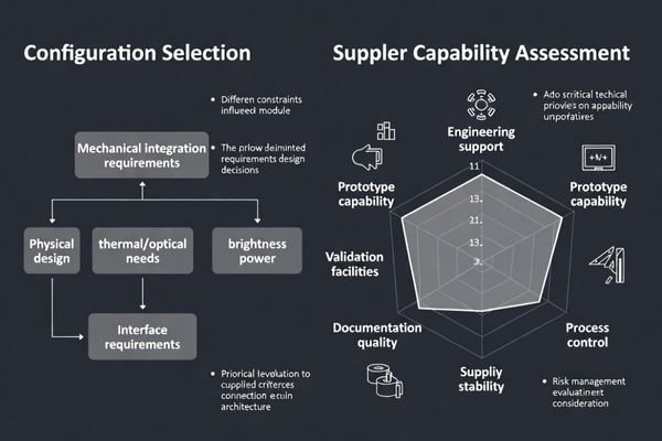
In my experience with custom module projects, supplier engineering depth matters more than manufacturing scale alone. The supplier must understand integration challenges, provide design validation support, maintain process discipline, and support long-term supply chain stability for industrial product lifecycles that often exceed consumer electronics timelines.
Because this workflow is centered on customization, I avoid a product selection table that adds little decision value when the answer is always “custom.” Instead, I use a workflow-fit checklist that aligns configuration choices with schedule, risk, and production outcomes: confirm the viewable window and allowable alignment drift, lock maximum Z-height with a worst-case tolerance stack and assembly process window, define the routing envelope and strain relief intent for the interconnect, and set a brightness target that remains readable after thermal steady-state with a clear derating rule. Then I evaluate supplier support by whether they can sustain prototype iteration cadence, provide validation evidence tied to acceptance criteria, document CTQ parameters and inspection gates, and enforce change control so substitutions do not silently alter optical, mechanical, or electrical behavior over the product lifecycle.
FAQ
What is the minimum information needed to start quoting and feasibility review?
I typically need the enclosure front opening and target viewable window, maximum Z-height, mounting and keep-out constraints, the host interface expectations, estimated cable length, power budget for the backlight, and the operating environment (temperature, ambient light, duty cycle) to define a realistic concept and risk list.
How do you avoid requirement changes causing repeated prototype loops?
I lock a constraint hierarchy early, define measurable acceptance criteria, and run changes through impact review on stack-up, thermal margin, and interface stability so we only iterate when the change is worth the schedule and tooling impact.
What are common causes of late-stage mechanical failure in custom modules?
The most common causes are underestimated local thickness peaks, missing tool/service access, unrealistic gasket or adhesive thickness assumptions, and cable routing that pinches or overstresses the interconnect during assembly.
What should be validated before committing to tooling and fixtures?
I validate stack-up clearance under worst-case tolerances, repeatable mounting and alignment, connector mating and strain relief, thermal steady-state behavior at target brightness, and basic stability under the expected EMI/ESD exposure.
How do you ensure mass production consistency across batches?
I recommend locking critical-to-quality parameters, defining inspection gates, controlling key suppliers, and enforcing a documented change control process so substitutions do not silently alter optical, mechanical, or electrical behavior.
When is customization the best option instead of adapting a standard module?
Customization is often best when the enclosure opening, Z-height, mounting constraints, or cable routing leave little margin, or when the product needs stable readability and reliability across demanding environments and long lifecycles with controlled change requirements.
Conclusion
Custom LCD module project success depends on systematic workflow management that converts requirements into testable specifications, reduces risks through targeted prototype phases, and validates mass production readiness through repeatability verification. The key is maintaining engineering discipline throughout the development cycle rather than rushing to production with unvalidated assumptions. As an engineer, I focus on early constraint definition, systematic risk reduction, and controlled change management to ensure projects reach mass production without expensive redesign cycles, using a repeatable workflow: requirements and constraints first, specifications with acceptance criteria next, prototype phases that burn down risk, and production readiness proven through repeatability and change control.
MEIDAYINGNUO provides comprehensive custom LCD module development support including requirements analysis, prototype planning, engineering validation, and production transition management. Our workflow emphasizes early risk identification, systematic validation, and quality control to ensure custom solutions meet performance requirements and production schedules. Contact our engineering team when developing custom display solutions that require disciplined project management and validation support.
✉️ info@lcdmodulepro.com
🌐 https://lcdmodulepro.com/
-
Exploring the components of a project input package can enhance your project planning and execution, ensuring better results. ↩
-
Learning about tolerance stack-up analysis is crucial for preventing assembly issues and ensuring product reliability. ↩
-
Defining measurable success criteria helps in tracking project progress and ensuring alignment with business goals. ↩
-
Understanding mechanical conflicts can help you avoid costly mistakes in your prototype development process. ↩
-
Exploring change control can help you grasp how to manage modifications effectively and maintain product performance. ↩