When an LCD display module shows fixed-position noise, diagnosing signal integrity should be one of the first engineering priorities. Unlike random noise that shifts with image content, fixed-position defects usually indicate repeatable data corruption somewhere in the display signal path. In many real integration cases, the visible symptom appears on the screen, but the actual fault point is located upstream in the source, cable, connector, PCB layout, grounding path, timing configuration, or EMI environment.
Diagnosing fixed-position noise on an LCD requires a structured signal integrity investigation. The most reliable method is to confirm that the defect is truly position-fixed, isolate the source, cable, and display path with known-good references, and then use electrical verification to identify whether the root cause is linked to impedance mismatch, timing margin, grounding, connector quality, or another weakness in the signal path.
Based on my LCD display module integration work at LCD Module Pro, I treat the LCD module as the receiving endpoint until upstream causes are excluded. The display is highly sensitive to the quality of the incoming signal. A signal can pass basic continuity checks and still be marginal enough to create repeatable bit errors because of jitter, attenuation, crosstalk, poor return path quality, or timing weakness. When these errors affect the same part of the incoming data stream repeatedly, the result often appears as noise locked to a specific area of the screen.
Reliable diagnosis should be measurement-based rather than assumption-based. A disciplined troubleshooting sequence1 that separates the source, transmission path, and panel reception stage is far more effective than replacing parts at random. This article explains how to confirm the symptom, isolate the likely fault domain, and use the right signal integrity methods to locate the actual root cause.
What Does Fixed-Position Noise Usually Mean on an LCD Display Module?
Before starting detailed troubleshooting, the first task is to define the symptom accurately. Fixed-position noise is not just a visual annoyance. It is an important clue about how and where the display data may be breaking down.
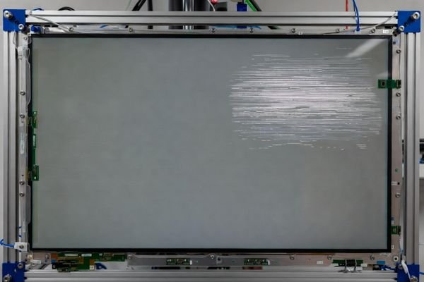
Fixed-position noise refers to repeatable visual artifacts such as sparkles, shimmering pixels, or fine lines that remain in the same physical screen location regardless of the displayed content. This usually indicates repeatable data corruption in the signal path rather than a fault in the image source itself.
When I troubleshoot this type of issue in the field, I first confirm that the noise is truly fixed in location rather than triggered by specific content. That distinction matters because it determines whether the investigation should focus on the image pipeline, the electrical path, or the panel-side receiver.
Differentiating Fixed vs. Content-Dependent Noise
It is essential to distinguish fixed-position noise2 from content-dependent noise. Content-dependent noise changes with the image, the color transitions, or the displayed pattern. For example, a defect that only appears in dark scenes or only during specific gradients should be investigated differently from a defect that always appears in the same corner or column of the screen.
The best way to make this distinction is to use static test patterns. Switch between full black, full white, red, green, blue, checkerboard, and grayscale patterns. If the defect remains in the same physical location across these patterns, the problem is more likely tied to repeatable data corruption in the transmission path or to panel-side reception sensitivity, not to the content itself.
Common Interpretations of the Symptom
Once the symptom is confirmed as position-fixed, the investigation should move toward signal integrity and interface-related causes. In many cases, fixed-position noise points to a weak lane, marginal timing, poor connector contact, grounding weakness, or PCB routing limitations that affect a repeatable portion of the incoming data.
In most fixed-position noise cases, the root cause is found in the signal path rather than in the LCD module itself. A panel can still light normally and display a stable image overall while one portion of the incoming data is being corrupted repeatedly. That is why engineers should begin by reviewing the electrical path from the source graphics output to the display input rather than assuming an internal panel defect.
What Signal Integrity Problems Commonly Create Fixed-Position Noise?
Fixed-position noise is usually not caused by total signal failure. More often, it is the result of a marginal high-speed path that still functions but no longer has enough signal margin to remain clean under all conditions.
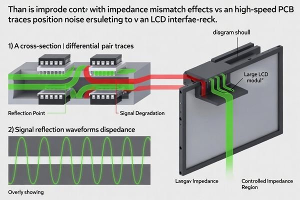
Common signal integrity causes of fixed-position noise include impedance mismatch in differential pairs, excessive jitter, poor PCB routing, crosstalk, oxidized or unstable connector contacts, inadequate grounding or shielding, and timing margins that are too tight for reliable data reception.
In real LCD module projects, these problems often emerge when the design is operating close to its limit, such as with longer cables, higher pixel clocks, tighter layout constraints, or noisier system environments. The LCD display module is often not creating the problem. It is exposing a weakness already present in the signal path.
Here are the most common fault mechanisms:
- Impedance Mismatch: LVDS and eDP interfaces depend on controlled differential impedance. If the PCB traces, cable, connector, or transition structure do not maintain the intended impedance, signal reflections can distort the waveform and create repeatable bit errors.
- Poor Differential Pair Routing3: Unequal pair length, spacing inconsistency, or poor return path design can create skew and reduce noise margin. A weak differential pair does not always fail completely; it may instead produce localized display defects.
- Crosstalk: Closely spaced high-speed lines or coupling from nearby clocks and switching nets can inject interference into display data paths. This can create stable visual artifacts if the interference repeatedly affects the same transmitted bits.
- Connector and Cable Issues: Oxidized contacts, damaged pins, unstable connector seating, broken shielding, or marginal cable construction can degrade the signal enough to create position-fixed noise without causing total image loss.
- Grounding and Power Noise: Poor return path integrity and local ground instability reduce receiver margin. If the panel-side receiver loses noise margin, certain portions of incoming data can become unreliable.
- Timing Margin Problems: Even when the display synchronizes and lights normally, marginal clocking or blanking configuration can reduce setup and hold margin enough to create repeatable data corruption.
A marginal cable can create repeatable visual defects without causing total image failure. That is why engineers should focus on signal quality and timing margin, not only on whether the display powers up successfully.
How Can You Tell Whether the Noise Comes from the Source, Cable, PCB, or Panel?
The fastest way to narrow down the fault point is to isolate the display chain with known-good references. A structured swap process is much more reliable than changing multiple variables at once.
The most effective way to locate the source of fixed-position noise is to swap the source, cable, and display path one at a time with known-good references. If the defect disappears after one controlled substitution, the original component or path becomes the primary suspect.
In practice, I recommend first setting up a repeatable test pattern that makes the defect easy to observe. Once the symptom is reproducible, isolate the fault path systematically.
| Potential Source | Symptom Behavior During Test | Next Diagnostic Step |
|---|---|---|
| Source (Host Board) | Noise disappears when a known-good source board is connected while using the same cable and display. | Review host board layout, output quality, signal termination4, power environment, and timing configuration. |
| Cable / Connector | Noise changes, disappears, or becomes worse when the cable is moved, reseated, or replaced. | Inspect connector pins, retention force, oxidation, shielding quality, and cable length or construction. |
| PCB / Interconnect Path | Noise remains tied to the original board path even after cable substitution. | Review routing quality, differential pair implementation, reference plane continuity, return path, and local noise sources. |
| LCD Module (Panel) | Noise remains in the same position even with a known-good source and cable under verified electrical conditions. | Reconfirm timing compatibility and input requirements. If validated, investigate panel-side receiver or compatibility sensitivity. |
If the defect disappears with a known-good cable, the original interconnect path is the likely cause. If the defect disappears with a known-good source, the original host path becomes the primary suspect. Only after upstream causes have been excluded should the investigation focus more heavily on the LCD module or panel-side receiver behavior.
If the results remain ambiguous, the issue may involve interaction between components rather than a simple single-part failure. In those cases, our engineering team can help review the signal chain and interpret the findings at info@lcdmodulepro.com.
Which Test Methods and Instruments Best Expose Signal Integrity Weakness?
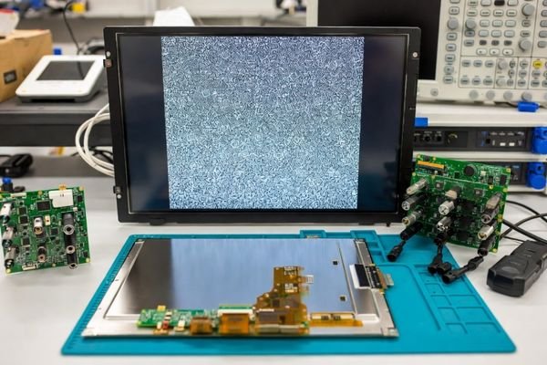
Component swapping helps isolate the fault domain, but electrical measurements are needed to explain why the problem is happening. That requires both the right visual test patterns and the right instruments.
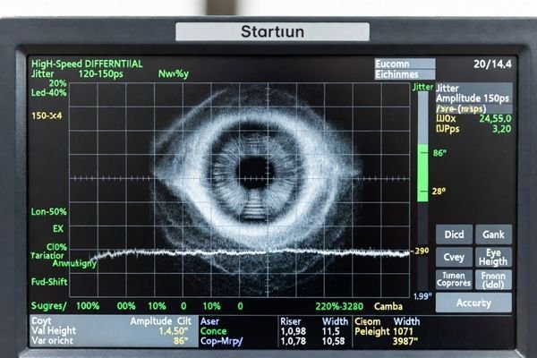
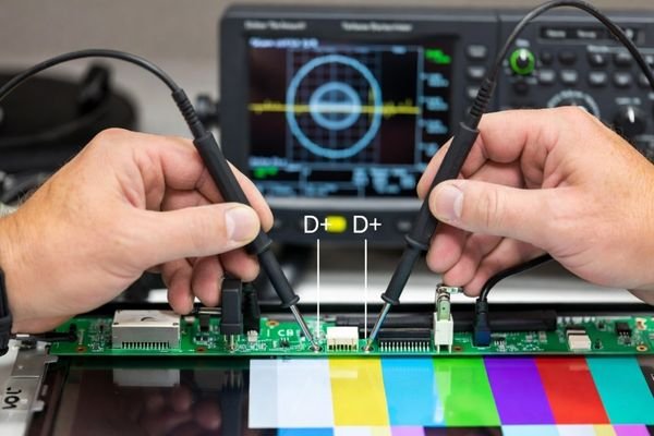
The most effective diagnosis combines repeatable visual test patterns with electrical verification using a high-speed oscilloscope. Eye-diagram review, jitter observation, and differential signal measurement are among the strongest methods for exposing signal integrity weakness in an LCD interface.
In actual engineering work, I treat diagnosis as a two-step process: reproduce the fault visually, then verify it electrically.
Visual Test Methods
Visual test patterns help determine whether the defect is tied to specific transitions, colors, or fixed coordinates on the display.
- Solid Color Screens: Full black, white, red, green, and blue screens help determine whether the noise is content-independent and fixed in screen position.
- Checkerboard Patterns: These are excellent for stressing the interface because they maximize data transitions and often expose timing or jitter weaknesses.
- Walking-Ones / Walking-Zeros Patterns: These are useful when investigating whether a specific data lane or bit position is weaker than the others.
- Grayscale and Fine Transition Patterns: These can reveal subtle repeatable corruption that does not always show up on coarse test screens.
Fixed-position noise usually indicates repeatable data corruption rather than content failure. The more repeatable the symptom is under controlled patterns, the easier it becomes to correlate the visual artifact with a transmission weakness.
Electrical Measurement and Instruments
Once the visual symptom is reproducible, electrical measurement becomes essential.
- High-Speed Oscilloscope: The oscilloscope should have enough bandwidth to capture the actual signal behavior with useful margin.
- Differential Probes: LVDS and eDP signals must be measured differentially to understand how the receiver sees the waveform.
- Eye Diagram Review5: Eye-diagram degradation is often the clearest electrical proof of signal weakness. A healthy signal shows an open eye with sufficient margin. A collapsing or distorted eye indicates jitter, reflection, attenuation, or noise coupling problems.
- Jitter Analysis: Jitter that grows under certain conditions can reduce timing margin and create repeatable bit errors.
- Power and Ground Observation: Measuring supply quality and local ground behavior can help identify whether the signal receiver is losing margin because of electrical noise rather than pure routing problems.
A panel may show a stable image and still suffer from marginal signal integrity. That is why electrical verification should always accompany visual symptom analysis when fixed-position noise is involved.
What Is the Most Effective Troubleshooting Sequence for Fixed-Position Noise?
The best troubleshooting sequence starts with symptom confirmation, then moves through the highest-probability external causes before considering lower-probability panel-side causes.
The most effective sequence is: 1) Confirm the symptom with repeatable test patterns, 2) Swap the cable and source with known-good references, 3) Inspect connectors and physical interconnects, 4) Verify grounding and shielding, 5) Review software and timing parameters, and 6) Perform electrical verification before concluding that the LCD module itself is faulty.
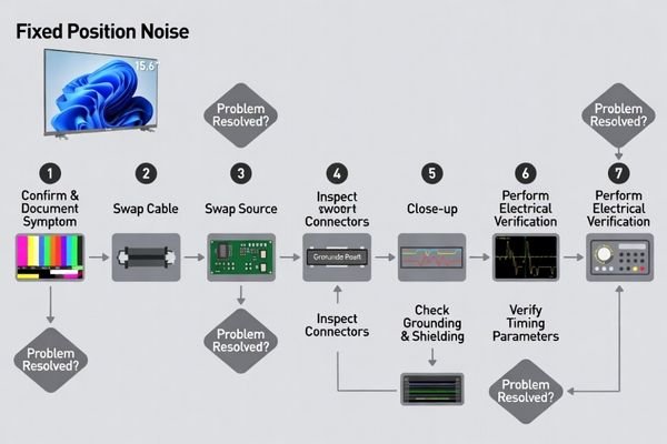
This is the step-by-step process I follow in practical engineering work:
- Reproduce and Document the Symptom: Use a stable pattern set and record exactly where the noise appears, how strong it is, and whether it changes with color, temperature, or operating mode.
- Swap the Cable First: A known-good, shorter, and higher-quality cable is often the fastest first check because cable and connector issues are common.
- Swap the Source Next: Keep the same cable and display, but drive the module from a stable reference source. This quickly separates host-path faults from downstream faults.
- Inspect Connectors Carefully: Check for bent pins, oxidation, incomplete insertion, unstable retention, dust contamination, or mechanical stress.
- Verify Grounding and Shielding: Review the return path, shield connection, and system grounding strategy. A weak ground path can reduce receiver margin significantly.
- Review Timing and Configuration: Confirm that clocking, mapping, initialization, and interface settings exactly match the display requirements. Even a small timing margin problem can create repeatable noise.
- Perform Electrical Verification: Use the oscilloscope, differential probing, eye diagrams, and jitter analysis to confirm where and why the signal is weak.
- Evaluate the Panel Side Last: Only after upstream conditions are validated should you conclude that the LCD display module or panel-side receiver is the true source of the problem.
This sequence matters because random, uncontrolled changes can hide the fault instead of exposing it. A structured sequence reduces false conclusions, shortens debug time, and helps teams distinguish between signal-path weakness, board-level design limits, environmental noise, and true module-side issues.
FAQ
Does fixed-position noise always mean the LCD display module is defective?
No. In many cases, fixed-position noise is caused by signal integrity issues, a faulty cable or connector, improper grounding, or incorrect timing settings that are external to the LCD module.
Why does the noise stay in the same area of the screen?
The noise is often caused by repeatable bit errors on a specific data lane or in a repeatable section of the data path. Since the same part of the pixel stream is affected each time, the defect appears locked in position.
Can a bad cable cause fixed-position noise instead of total signal loss?
Yes. A marginal cable can degrade signal quality enough to create repeatable data errors without causing a full image failure or black screen.
What is the fastest way to narrow down the fault point?
The fastest first step is usually to swap the display cable with a known-good reference cable while keeping the same source and display. If the defect remains, swap the source next.
Can incorrect timing settings create fixed-position visual noise?
Yes. Even if the display synchronizes and shows an image, marginal timing can reduce setup and hold margin and create repeatable visual corruption.
Should EMI be considered if the noise appears only under certain working conditions?
Yes. If the defect appears or worsens when switching regulators, motors, fans, relays, or wireless functions are active, EMI should absolutely be included in the diagnosis.
Conclusion
When an LCD display module shows fixed-position noise, the most effective diagnosis is to isolate the signal chain step by step before suspecting the panel. In most real projects, the root cause is found in the cable path, connector condition, grounding, timing margin, or other signal integrity weaknesses rather than in the LCD module itself.
At LCD Module Pro, we recommend a structured, measurement-based troubleshooting process built on controlled symptom reproduction, known-good substitutions, connector and grounding review, timing verification, and oscilloscope-based electrical analysis. By treating fixed-position noise as a system-level signal integrity problem instead of a simple display defect, engineers can locate the true fault point more accurately, reduce unnecessary module replacement, and improve the long-term reliability of the final LCD integration.
✉️ info@lcdmodulepro.com
🌐 https://lcdmodulepro.com/
-
Learning about a disciplined troubleshooting sequence can enhance your approach to diagnosing LCD display problems systematically. ↩
-
Understanding fixed-position noise is crucial for troubleshooting display issues effectively, ensuring accurate diagnosis and repair. ↩
-
Learn how routing can impact display quality and reliability, helping you design better systems. ↩
-
Exploring signal termination will enhance your knowledge of preventing signal integrity issues in electronic circuits. ↩
-
Discover the importance of eye diagrams in assessing signal quality and identifying potential weaknesses. ↩