In custom device development, LCD module integration is not only an electrical task. A display can have the right size, resolution, brightness, and interface, but still create serious problems if it does not fit the enclosure, mounting structure, cable path, or front-panel design.
Mechanical integration should be reviewed early because it affects module selection, customization feasibility, assembly reliability, and production consistency. Key points include active area alignment, enclosure opening, module thickness, mounting method, FPC direction, connector clearance, and touch or cover glass structure.
In LCD module projects, many delays come from small mechanical conflicts1 that were easy to miss during early selection. A datasheet may show outline dimensions, but it does not always reveal how the module will behave inside a real device with PCBs, brackets, cables, gasket structures, and a front panel.
A useful mechanical review looks at the LCD module as part of the device structure, not as a separate part. The goal is to make sure the display can be mounted, aligned, connected, sealed, assembled, and serviced without creating hidden risks.
Why Mechanical Integration Should Be Reviewed Early
Mechanical fit should be one of the first review gates before an LCD module is finalized. If a mismatch appears during prototype assembly, the project may need enclosure changes, cable redesign, a different mounting method, or even a different LCD module.
Mechanical integration is not a final assembly detail. It is an early design decision that helps prevent enclosure interference, blocked viewing area, cable stress, mounting instability, and late-stage redesign.
In early mechanical reviews, our engineering team usually checks the enclosure opening, active area alignment, viewing area, module outline, connector height, FPC direction, mounting method, and available internal clearance before recommending a module direction. These details often decide whether a standard LCD module can be used or whether a more customized structure is needed.
For applications such as transportation systems, industrial control devices, smart terminals, and measuring equipment, the mechanical requirements can be very different. A display that fits one enclosure may not work in another if the viewing area, cable path, cover glass, or mounting structure changes.
Beyond Datasheet Dimensions
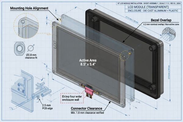
A common mistake is to judge mechanical fit only by outline length and width. Real assembly is more three-dimensional. Connector height, FPC exit direction, screw boss location, bracket clearance, and cover glass stack-up can all create conflicts.
Early review of mechanical drawings, 3D models, and cable layout helps catch these issues before hardware is ordered. This reduces the chance of discovering a conflict only after the enclosure tooling or prototype parts are already made.
Impact on Project Timeline and Cost
Mechanical mismatch found late can trigger several changes at once: a modified housing, a custom FPC, a new bracket, a different cover glass, or a replacement LCD platform. Each change adds engineering time and usually delays validation.2
A front-end mechanical review is a low-cost step compared with redesigning the enclosure or rebuilding samples after the first prototype fails to assemble.
Define the Enclosure Opening, Active Area, and Viewing Area
One of the most common mechanical integration problems is confusion between the active area, viewing area, enclosure opening, and full module outline. These dimensions are related, but they are not the same.
A clean mechanical design requires the LCD active area, enclosure opening, cover glass window, and visible UI area to be aligned. If they are not reviewed together, useful pixels may be covered, the image may look off-center, or the front panel may expose unwanted bezel areas.
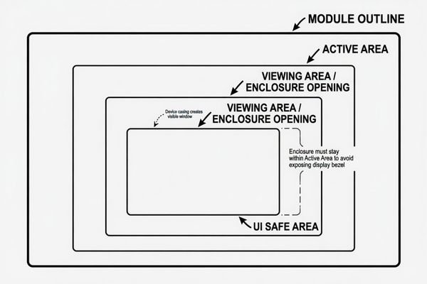
When reviewing front-panel design, we usually compare the LCD active area, cover glass window, enclosure opening, and UI safe area together. This helps prevent problems where the display technically fits, but part of the useful image area is covered by the bezel, black border, or front housing.
| Term | Meaning | Why It Matters |
|---|---|---|
| Active Area | The pixel region that displays the image | Defines where useful image content appears |
| Viewing Area3 | The visible window after assembly | Prevents important UI content from being blocked |
| Module Outline | The full physical size of the LCD assembly | Determines enclosure fit and mounting space |
| Cover Glass Window | The transparent area of the front glass | Affects appearance, alignment, and visible edge control |
The enclosure opening should expose the intended display area without showing internal structures. It should also leave enough tolerance for assembly variation. In production, a design that looks centered in one sample may shift slightly because of adhesive thickness, gasket compression, glass tolerance, or bracket positioning.
Check Module Thickness, Mounting Method, and Tolerance
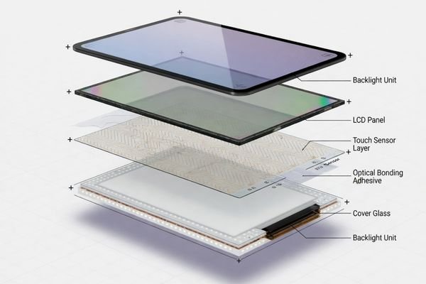
Module thickness is often more complex than the LCD panel thickness shown in a datasheet. The final stack may include the LCD panel, backlight, metal frame, touch sensor, adhesive layer, cover glass, gasket, and mounting hardware.
The final module thickness and mounting method must match the available enclosure depth, assembly process, and tolerance stack-up. A module that fits the front opening may still fail if the Z-height or mounting structure is not reviewed.
Mounting should be selected based on the device structure, not only the LCD module frame. Rear mounting, side mounting, brackets, adhesive bonding, and front-panel bonding each create different assembly and serviceability conditions.
| Mounting Method | Typical Use | Key Checkpoint |
|---|---|---|
| Rear mounting | Module fixed from behind the front panel | Rear access, screw position, gasket compression |
| Side mounting | Brackets or side holes attach to chassis | Side clearance and frame rigidity |
| Adhesive bonding4 | Module or cover glass bonded to housing | Alignment control and serviceability |
| Custom bracket | Used when enclosure structure is fixed | Tolerance, vibration, assembly sequence |
Tolerance stack-up should be checked before design freeze. Cover glass thickness, adhesive thickness, gasket compression, screw boss position, and housing tolerance can all shift the final display position. A single hand-built sample may fit, but production needs repeatable assembly clearance.
Plan FPC Direction, Connector Position, and Cable Routing
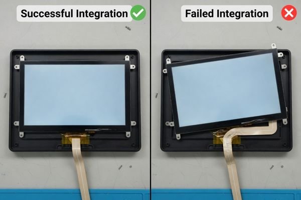
A display may be electrically compatible with the controller board, but it still cannot be used reliably if the FPC or cable cannot be routed safely. Cable routing is both an electrical and mechanical issue.
The FPC exit direction, connector position, cable bend radius, and routing path should be checked with the mainboard layout and internal chassis. Poor cable routing can cause stress, signal instability, assembly difficulty, or service problems.
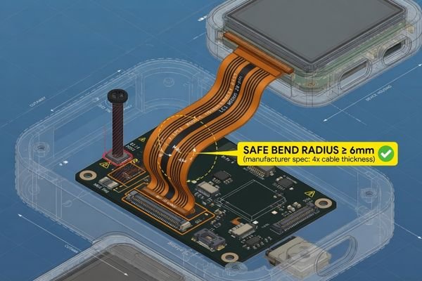
For cable routing review, our engineering team usually checks the FPC exit direction, connector position, bend radius, cable length, nearby heat sources, high-current lines, metal edges, and assembly access. A cable route that works in CAD may still create stress or serviceability problems during real assembly.
FPC and Connector Placement
The FPC direction should match the mainboard position whenever possible. If the cable exits toward a chassis wall or a high component area, it may require a sharp bend or become compressed after assembly.
Connector access also matters. A connector that is difficult to reach may slow production or increase handling damage. In compact products, the cable route should be reviewed together with brackets, screws, heat spreaders, batteries, and other internal parts.
Safe and Reliable Cable Routing
The cable path should avoid sharp bends, moving parts, high-current lines, hot components, and sharp metal edges. It should also leave enough space for assembly workers to connect and lock the cable without forcing it.
When the internal layout is tight, it is better to Discuss your custom display project before the LCD module, FPC, and mainboard positions are fixed. Early review can help determine whether a custom FPC, adapter board, or connector direction change is needed.
Consider Touch, Cover Glass, and Optical Bonding Structure
Touch panels and cover glass should not be treated as accessories added after LCD selection. They become part of the mechanical structure and directly affect the final stack height, front-panel design, visible area, and assembly tolerance.
Touch, cover glass, and optical bonding change the mechanical design of the LCD module. They affect thickness, viewing area, black border design, cable routing, bonding method, impact resistance, and final assembly alignment.
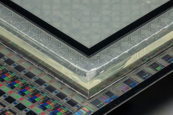
A PCAP touch panel adds sensor layers, a touch controller, and an additional cable path. Cover glass adds thickness and may require black border printing to hide internal structures. Optical bonding improves structural strength and readability, but it also creates a bonded stack that must be planned before the enclosure depth and front opening are finalized.
When high brightness or outdoor readability is part of the project, the front stack becomes even more important. You can Explore high brightness display modules to compare display directions, but the final design still needs to account for cover glass, bonding, reflection, touch sensitivity, and thermal behavior.
Air bonding may allow easier service or lower cost, while optical bonding may be preferred for better contrast, impact resistance, and reduced internal reflection. The right choice depends on the product environment, front-panel design, service requirement, and production plan.
Validate Mechanical Assembly Before Production
A CAD model can reduce risk, but it cannot replace physical validation. Before production, the LCD module should be checked inside the actual enclosure with the planned mounting method, cable path, cover glass stack, and controller board position.
Mechanical validation should confirm fit, alignment, cable routing, mounting stability, serviceability, and repeatable assembly. A sample that fits once is useful, but production readiness depends on tolerance control and stable assembly behavior.
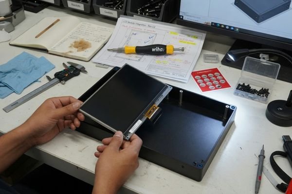
Before production, we usually verify the LCD module inside the actual enclosure with the planned mounting method, cable route, cover glass stack, touch structure, and controller board position. A sample that fits once on a bench is useful, but production readiness depends on repeatable assembly, tolerance control, and stable mechanical alignment.
| Validation Item | What to Check |
|---|---|
| Fit check | Module inserts without force or interference |
| Alignment | Active area and viewing window stay centered |
| Cable routing | FPC has safe bend radius and no compression |
| Mounting stability | Module does not move under handling or vibration |
| Serviceability | Module can be removed without damaging nearby parts |
This validation should happen before design freeze and again before volume production. It helps confirm that the display is not only mechanically possible, but also practical for assembly, inspection, and long-term product use.
For projects that need a more structured review, custom LCD module engineering can help connect mechanical requirements with module selection, sample validation, and production planning.
Mechanical Integration FAQ
What mechanical information is needed for a custom LCD module?
Useful information includes the enclosure drawing, front opening size, target active area, viewing area, maximum module thickness, mounting method, connector direction, cable route, cover glass requirement, touch requirement, and expected production plan.
What is the difference between active area and viewing area?
The active area is the pixel display region of the LCD panel. The viewing area is the visible window after the module is assembled into the product. Both should be checked with the enclosure opening and cover glass design.
Can the FPC direction or connector position be customized?
In some projects, FPC direction, cable design, connector position, or adapter board arrangement can be adjusted. Feasibility depends on the LCD panel structure, timing requirements, production quantity, and project budget.
Does touch integration affect mechanical design?
Yes. Touch integration affects thickness, front-panel structure, cover glass size, bonding method, cable routing, and sometimes touch sensitivity. It should be reviewed before the enclosure design is finalized.
When should mechanical integration be reviewed?
Mechanical integration should be reviewed before prototype development, especially when enclosure space is fixed, touch or cover glass is required, or the LCD module must fit a non-standard front-panel design.
Conclusion
Mechanical integration is a core part of custom LCD module development. The display must fit the enclosure, align with the viewing window, route cables safely, support the selected mounting method, and work with touch or cover glass structures without creating assembly risk.
Not sure whether your LCD module can fit your device structure? Start by preparing the mechanical drawing, target display area, connector direction, cover glass requirement, mounting method, and production plan. Our engineering team can help review the structure before the module is finalized.
→ Start your custom display project
✉️ info@lcdmodulepro.com
🌐 https://lcdmodulepro.com/
-
PMC. “Misalignment in Mechanical Interlocking Heterogeneous Integration.” ↩
-
World Scientific. “Engineering Change Impact on Product Development.” ↩
-
Newhaven Display. “Understanding Display Viewing Angles.” ↩
-
Beetronics. “Display Bonding Methods and Their Impact on Performance.” ↩