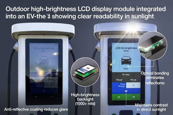
Choosing the right outdoor high-brightness LCD display module for an EV charger is less about one “nits” number and more about making the whole stack behave in sunlight, heat, humidity, and messy power events.
If it looks great on the bench but turns into a mirror outside, it’s usually not “a bad screen”—it’s a system mismatch. Readability, thermal path, sealing, interface timing, and ESD/EMI all interact, and the display module is the first thing blamed when any link is weak.
In my LCD display module integration work at LCD Module Pro, I’ve seen many EV charger projects struggle not because the chosen display module was “bad,” but because integration assumptions didn’t survive the outdoor environment. A screen that looks brilliant in the lab can become hard to read—or fail early—once it’s dealing with real sun, heat, humidity, cleaning chemicals, and day/night thermal cycling.
Success usually comes from system-level thinking1: how the optical stack manages reflections, how the enclosure spreads heat, how the mechanical stack keeps moisture out for years, and how the electrical interface behaves under real-world power conditions.
What makes an EV charger “outdoor” harsh for an LCD module?
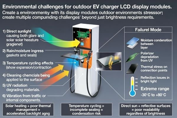
The "outdoor" environment for an EV charger combines thermal stress, direct sun exposure, moisture, and mechanical wear, creating a uniquely harsh operating condition for an LCD display module.
Outdoor isn’t one problem—it’s a stack of problems: glare + solar heat + humidity + vibration + cleaning. If your tolerance stack-up or sealing plan is weak, moisture and dust eventually find a way in. And when readability drops or failures start, the display module gets blamed first.
Based on the projects I support with OEMs, the stressors don’t show up one at a time—they compound. For example, solar loading doesn’t just hurt readability; it adds real thermal load, and that extra heat accelerates backlight aging and shifts optical performance over time.
Thermal and Optical Stress
Direct sunlight is a double threat. First, intense ambient light can wash out the display and make the interface unreadable because contrast collapses in bright conditions. Second, solar load2 heats the entire display stack. Under the wrong mechanical and thermal conditions, the stack temperature can climb high enough to cause visible performance issues (including approaching the liquid crystal clearing point), and it can also accelerate degradation of backlight LEDs and optical films—reducing brightness and lifetime. Cold weather is the other side of the same problem: response slows, ghosting becomes noticeable, and users assume something is “broken” even when it’s just physics.
Moisture, Chemical, and Mechanical Wear
Outdoor enclosures are rarely “perfectly sealed forever.” Temperature cycling causes pressure changes that can breathe moist air through weak points, and condensation risk becomes real if the stack traps moisture. That can show up as haze, blotches, or long-term damage to polarizers and adhesives. The front surface also has to survive UV exposure, cleaning chemicals, and occasional impact or vandalism. Meanwhile, vibration—from traffic, doors, fans, or contactors—slowly works on connectors, cable strain relief, and mounting points until you get intermittent faults that are painful to reproduce on a bench.
How bright is “bright enough” for outdoor EV chargers?
"Bright enough" is not a single number; it’s a strategy that combines backlight luminance with reflection control so the display stays readable in worst-case ambient light.
I start from readability, not nits. If reflections dominate, extra brightness becomes expensive heat and faster aging. Define worst-case sun, viewing distance, and angles, then balance luminance with AR/AG surfaces and (if needed) optical bonding so contrast holds up outdoors.
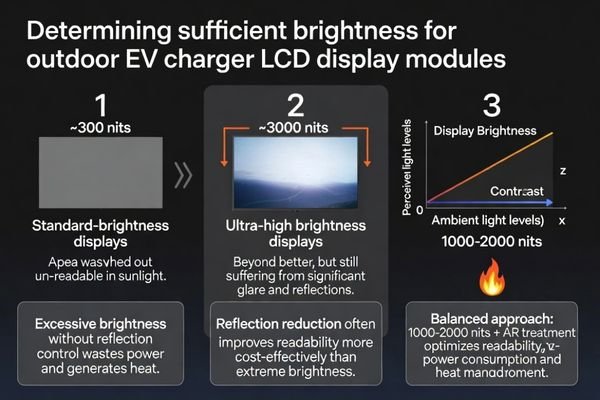
From an engineering standpoint, I usually steer teams toward thinking in terms of contrast in sunlight rather than nits alone. A module with strong reflection control can look more readable than a higher-luminance module with a reflective front surface, because the bright sky and sun reflections can overwhelm the display output. One common mistake is specifying extreme brightness without planning for the thermal consequences inside the enclosure. If heat can’t be managed, systems often end up dimming to protect themselves—so you paid for brightness you can’t actually use. In many EV charger deployments, a balanced approach (often a common target range around 1000–2000 nits, pending confirmation by environment and optics) plus good reflection control3 ends up being more reliable and energy-efficient than “maximum nits at any cost.”
Which optical and cover-lens choices actually improve sunlight readability?
Sunlight readability improves most effectively by reducing reflections with the right cover lens treatments and optical bonding, which can boost perceived contrast more than simply increasing backlight brightness.
Optics is the real lever outdoors. A well-treated cover lens plus optical bonding can raise perceived contrast dramatically and reduce internal fogging risk. The trade-off is serviceability and cost—so decide early whether the charger needs touch, gloves support, and field-replaceable front assemblies.
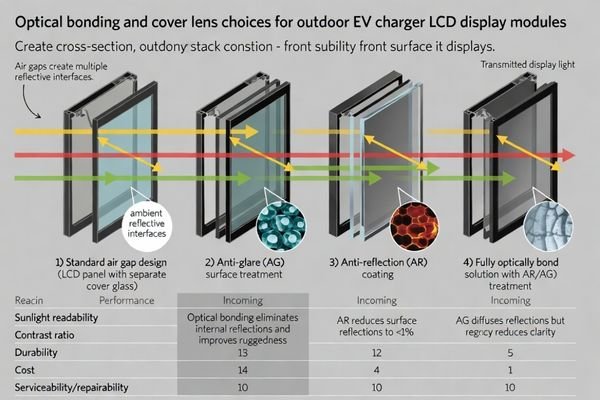
When I troubleshoot field issues, a common complaint is a “dim” display that is actually plenty bright—it’s just being washed out by reflections. The air gap between the cover lens and the module is often the culprit because it creates multiple reflective interfaces.
| Optical Solution | Primary Benefit | Key Trade-Offs | Best For |
|---|---|---|---|
| Standard Air Gap | Lowest cost, easy rework | High internal reflections, lower contrast, risk of internal fogging | Cost-sensitive applications in shaded or semi-outdoor locations. |
| Anti-Glare (AG) Cover Lens | Diffuses reflections, reduces glare | Can slightly reduce sharpness and show “sparkle”; lower cost than AR | Environments where distinct reflections are a problem but cost is a major factor. |
| Anti-Reflection (AR) Coating | Minimizes surface reflections, maximizes contrast | Higher cost; may show fingerprints unless paired with oleophobic treatment | Direct sunlight applications where clarity and contrast are required. |
| Optical Bonding (OCA/OCR)4 | Eliminates internal reflections, improves contrast and ruggedness | Highest cost; harder to rework/service | The most demanding outdoor environments; improves readability and durability. |
In practice, combinations are common. For a high-end EV charger, I often see a stack that uses optical bonding plus a cover lens with reflection-control treatment, tuned to the UI requirements and service model. The main point is to decide early: if you design around a bonded stack, you should also design around how it will be built, validated, and serviced.
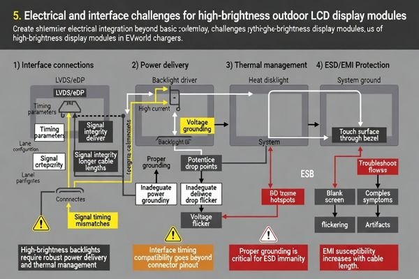
What electrical and interface details are most likely to cause integration issues?
The most common integration issues come from interface timing and mapping mismatches, pinout/connector surprises, and underestimating the power and control needs of a high-brightness backlight—often discovered late.
Most “mystery failures” come from the signal chain and power domains, not the LCD glass. Lock timing, mapping, connector, and pinout early. Then validate dimming, flicker, EMI, and brownout behavior inside the real enclosure—bench success doesn’t guarantee field stability.
In my work, I’ve learned that “electrically compatible” on a datasheet isn’t the same as “integration-ready.” The fine print is where schedule risk lives. If you’re building an EV charger and want to de-risk display module integration, our team can help review your schematics and system architecture; feel free to reach out to us at info@lcdmodulepro.com.
Signal Chain and Interface Risks
An “LVDS” or “eDP” label isn’t universal. You still need to verify timing parameters, lane configuration, and data mapping between the host processor and the display module’s timing controller. A common failure is when the mainboard output doesn’t quite match the module’s expected input range, leading to a blank screen or random artifacts. Cable length and quality matter too: a long, poorly shielded cable that works on the bench may fail EMI testing or show signal integrity issues once it’s routed through a metal enclosure with real noise sources.
Power, Dimming, and ESD Considerations
A high-brightness backlight5 is a meaningful power load. The supply must deliver the required current without excessive drop or ripple, because that’s a fast path to flicker. The dimming signal (often PWM) should be clean and high enough in frequency to avoid visible flicker or audible noise. And because the front surface of a charger is an easy target for ESD events, you want a grounding strategy that’s intentional: how the front lens, bezel, chassis, and module reference ground tie together matters a lot for robustness.
My practical selection checklist for outdoor high-brightness modules for EV chargers
This checklist is the process I use to de-risk an outdoor display module selection by focusing on integration reality, not just component specs.
I keep the order simple: readability → thermal/power → sealing/mechanics → interface/timing → ESD/EMI → lifecycle. The two mistakes I see most are “brightness without reflection control” and “datasheet compatible means done.” Fix those early and projects get calmer fast.
When I’m brought in to help select a module for a new EV charger design, I try to keep the order simple: readability first, then thermal/power, then sealing/mechanics, then interface/timing, then ESD/EMI, and finally lifecycle risk.
-
User Experience & Readability:
Does the size and resolution fit the UI design for the intended viewing distance? More importantly, what is the optical strategy? I like to decide early whether we’re relying on raw brightness, reflection control (AR/AG), optical bonding, or a mix—based on worst-case sunlight, viewing angles, and how “glossy” we can tolerate the front surface to be. -
Interface & Timing Risk:
What interface can the mainboard reliably output in your real design (not just in theory)? I usually aim for a module that matches this natively to avoid fragile converter boards. I also verify the connector details, pinout, signal mapping, and cable-length margin early—before the mechanical design locks you in. -
Power & Thermal Management:
High brightness costs power and generates heat. I always ask for a clear power budget6 at maximum brightness and a realistic plan for moving that heat into the enclosure. This includes understanding any thermal derating behavior—how brightness, color, and lifetime shift at elevated operating temperatures—so you don’t get surprises after deployment. -
Mechanical Integration & Serviceability:
How will the module mount, and how will the front lens stack seal over time? I look at mounting points, gasket strategy, and tolerance stack-up, but I also ask the uncomfortable question: if the display needs replacement, can a technician do it without turning a field repair into a full teardown? If serviceability matters, the optical and mechanical decisions have to support it. -
Reliability & Validation:
I want to see a validation story that matches outdoor reality: temperature cycling, high-humidity soak, vibration, long burn-in, and ESD checks around the front lens/touch area. This is where early assumptions get tested, and it’s also where weak integration choices show up before you ship volume. -
Supply Chain & Lifecycle Management:
EV chargers are long-lifecycle products, so I always ask about End-of-Life planning and the availability of alternate paths (mechanically and electrically). A supplier like LCD Module Pro who can support long-term supply planning and customization can reduce lifecycle risk—especially when you need continuity without redesigning the entire front assembly.
FAQ
Do I really need a “sunlight readable” module for an outdoor EV charger?
If the charger faces direct sun for long periods, “sunlight readable” is usually worth it, but don’t treat it as brightness only—reflection control (lens treatment and optical stack) often decides real readability more than a single nits number.
Will higher brightness always solve washout?
Not always. If glare and reflections dominate, adding brightness can just add heat and power draw while the screen still looks gray; combining moderate brightness with anti-glare/anti-reflection and bonding can be a better balance.
What interface checks prevent late-stage surprises?
Confirm the mainboard’s actual output (interface type, lane/channel, timing), then verify connector, pinout, cable length margin, and any backlight control signals early—before the mechanical design is locked.
Do optical bonding and coatings affect serviceability?
Yes. Bonding and coatings can improve outdoor readability and sealing, but they can also make rework harder; if field replacement matters, design the front stack so replacement is controlled and feasible.
What reliability tests matter most for chargers?
Temperature cycling, high-humidity soak, vibration, ESD checks around the front lens/touch area, and long burn-in are the usual “truth serum” for outdoor modules; they reveal drift and weak points early.
How do I avoid EOL risk for long-lifecycle charger projects?
Choose a module with a clear supply plan and an alternative path (mechanical and electrical), and keep key constraints documented so you can migrate without redesigning the whole front assembly.
Conclusion
Selecting an outdoor high-brightness LCD display module for an EV charger is a system decision, not a “pick the highest nits” decision. The display has to stay readable in sunlight, manage heat without sacrificing lifetime, keep moisture out over years of cycling, and remain electrically stable through real-world EMI/ESD and power events.
If you want to de-risk the integration, LCD Module Pro can review your optical stack, thermal/power budget, sealing approach, and interface timing so you don’t discover problems after the enclosure is locked. If you need a quote or datasheet, feel free to contact us.
✉️ info@lcdmodulepro.com
🌐 https://lcdmodulepro.com/
-
Exploring system-level thinking can enhance your approach to designing robust electronic systems that withstand real-world challenges. ↩
-
Understanding solar load is crucial for optimizing display performance in bright conditions, ensuring longevity and clarity. ↩
-
Understanding reflection control is crucial for optimizing display readability in various lighting conditions. ↩
-
Learn about the advantages of optical bonding for ruggedness and readability in demanding outdoor conditions. ↩
-
High-brightness backlights significantly impact power load and performance. Discover essential power management strategies in this resource. ↩
-
A clear power budget is crucial for managing heat and performance in displays; this link will provide essential insights. ↩