
Outline dimension defines the physical envelope of LCD modules that determines mechanical fit constraints, clearances, and assembly compatibility within enclosure designs.
Outline dimension is the LCD module’s mechanical envelope: the outer boundary that must fit your enclosure opening, brackets, seals, and keep-out areas. It is not an optical spec like active area. If the outline is wrong—or if clearances ignore tolerance stack-up, coatings, and gasket compression—the module may not seat flat, may stress the glass/frame, or may block connectors and cables.
Mechanical fit failures are expensive because they often appear late: during pilot build, ramp, or first service events. Teams can meet optical targets and still lose reliability if the module is forced into a tight opening, clamped unevenly, or constrained without room for cable routing and tool access. Treat outline dimension as the mechanical contract between the module and the enclosure, then validate that contract under worst-case tolerances1 and real assembly conditions.
What is "outline dimension" in an LCD display module?
Outline dimension represents the complete physical envelope of an LCD module defining spatial requirements and mechanical interface boundaries for integration design.
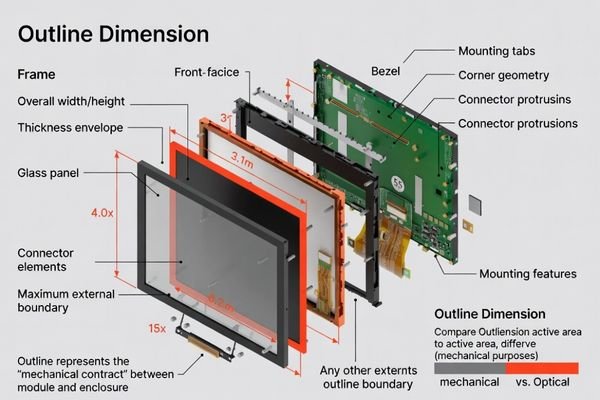
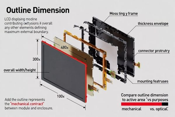
Outline dimension describes the module’s maximum external boundary that occupies space in your enclosure. It includes overall width and height, and often the thickness envelope and any protrusions that affect fit. Unlike active area, it exists to prevent interference with openings, bezels, brackets, and adjacent parts. A correct outline definition is the foundation for CAD layout, mounting placement, and tolerance stack-up for reliable assembly.
In practice, outline should be read as an envelope, not a single rectangle. Corner geometry, edge chamfers, metal frame extensions, and connector volumes can all become the limiting boundary. If you only design to nominal width/height, you can miss the true interference points that appear during insertion, seating, or cable connection. A good outline definition2 makes the “space claim” explicit so mechanical design can plan clearances confidently.
Physical Boundary Definition
Outline dimension should cover the maximum external boundaries of the module, including glass edges, frame overhangs, connector protrusions, and any mounting tabs or locating features that extend beyond the main body. These details often determine whether the module can pass through an opening and sit fully down without contact. For fit planning, treat protrusions as part of the envelope and define their keep-out needs clearly.
Mechanical Interface Requirements
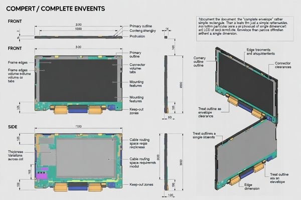
The outline interacts with brackets, gasket seats, bezel openings, and nearby components, so it must support the actual assembly sequence. A module can “fit through” an opening but still fail if the outline conflicts with a bracket during seating or if connector clearance is insufficient for cable bend radius. Defining interfaces around the outline helps avoid late surprises in fastening access, sealing integrity, and service removal paths.
Why does outline dimension decide mechanical fit?
Mechanical fit depends on the relationship between module envelope and enclosure constraints, making outline dimension the governing factor for assembly feasibility and stress-free integration.
Mechanical fit is governed by the module envelope relative to the enclosure opening, bracket positions, and keep-out zones, so outline is the first constraint that decides whether parts can assemble without interference. Even small outline mismatches can prevent flat seating, introduce stress into the glass/frame, or block connectors and cables. Because both module and housing vary in production, fit depends on worst-case stack-up, not nominal CAD.
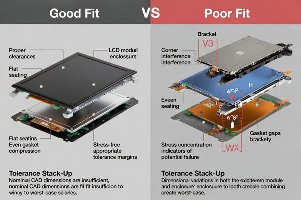
A “tight but workable” fit in one build can become a cracked cover lens or warped frame in another when tolerances stack the wrong way. Mechanical stress can also degrade optical appearance (light leakage, uneven borders) and long-term reliability (intermittent connectors, seal fatigue). When the outline envelope is defined and cleared properly, the module seats predictably, loads distribute correctly, and assembly remains repeatable3 across manufacturing variation.
Which mechanical references and tolerances should be defined around the outline?
Proper outline specification requires systematic definition of dimensional references, tolerance allocation, and coordinate systems that ensure predictable assembly outcomes.
To make fit predictable, define outline size with tolerances, the datum scheme used to locate the outline in the assembly, and keep-out regions for connectors, cables, and tools. Specify mounting hole/tab locations to the same datums, plus flatness/coplanarity if the module seats on a gasket or frame. When cover lens, bezel, foam, and bracket contribute to the envelope, use one coordinate system and tolerance for the real constraints, not nominal centering.
Fit drawings should answer three questions without interpretation: where the module boundary is, how it is located in the product, and what space must remain free for connectors and service. Mixed coordinate origins across suppliers are a common source of “same numbers, different meaning.” Establish one datum strategy4 that matches how the module is constrained during assembly, then allocate clearances using worst-case analysis so production parts remain interchangeable.
| Reference Category | Key Specifications | Tolerance Considerations | Integration Impact |
|---|---|---|---|
| Outline Envelope | Overall width, height, thickness | Manufacturing variation plus assembly clearance | Primary fit constraint and interference prevention |
| Datum Features | Reference edges, corners, or mounting points | Positional accuracy and repeatability | Assembly alignment and service accessibility |
| Keep-Out Zones | Connector, cable, and tool clearances | Dynamic requirements plus safety margin | Service feasibility and operational access |
| Mounting Interfaces | Hole patterns, tab locations, gasket seating | Fastener access and load distribution | Structural integrity and stress management |
Systematic reference definition ensures that mechanical fit requirements and optical alignment needs are coordinated while maintaining manufacturing feasibility and service accessibility throughout product lifecycle.
What are the most common fit failures caused by outline mistakes?
Outline-related fit failures typically manifest as interference issues, stress-induced problems, or assembly difficulties that compromise functionality and serviceability.
Common failures include corner or radius interference, insufficient clearance for connector backshells and cable bend radius, and uneven seating that creates stress, light leakage, or cracked cover components. Another frequent issue is “fits in CAD, fails in production,” where stack-up plus coating thickness, gasket compression, or bracket warp removes the margin. Always verify insertion, seating, and extraction paths with worst-case parts and real assembly sequences.
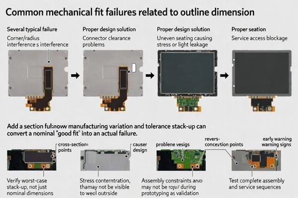
Many fit issues surface only when production variability and real processes enter the picture. A bracket that is slightly warped, a gasket that compresses more than expected, or a coating that adds thickness can turn a comfortable nominal design into an interference condition. Service is another trap: a module may install once, but removal may require force that damages parts or degrades sealing. Validate both assembly and service motions early.
I’ve observed that outline-related failures often develop during production or service rather than initial prototyping because real-world manufacturing variation, assembly processes, and service conditions expose margin inadequacies not apparent in nominal CAD analysis. For complex mechanical integration requiring systematic outline analysis and fit validation during LCD module development projects demanding precise mechanical coordination and assembly reliability, engineering teams can contact info@lcdmodulepro.com when outline dimension challenges require specialized expertise in tolerance analysis, assembly process optimization, and service accessibility design5.
Interference and Clearance Issues
Interference typically shows up at corners, radii, or local protrusions that were not included in the envelope model. Connector clearance is also commonly underestimated: backshell depth, cable bend radius, and strain-relief hardware require space that changes with routing and service access. Avoid designing to a “static rectangle” and instead define keep-out volumes that include cable motion and tool access under worst-case tolerance.
Assembly and Service Problems
If installation requires force, the module is being used as a structural element, which increases stress risk and reduces repeatability. Uneven seating can create gaps that lead to leakage and can also shift load to fragile areas. Service failures often come from missing extraction paths or blocked fasteners, especially once cables and seals are in place. Validate assembly sequence, seating confirmation, and clean removal using production-representative tooling.
How do you select and validate LCD module outlines for custom mechanical integration?
Effective outline selection requires systematic approach treating outline as mechanical contract while validating fit through representative prototyping and tolerance analysis.
Start by treating outline as the mechanical contract: confirm the full envelope (thickness stack, protrusions, connectors), then design openings, mounts, and keep-outs using worst-case tolerance stack-up. Validate with representative prototypes that include real bracket stiffness, gasket compression, cable routing, and service tools, since these often dominate fit. Finally, lock a repeatable datum and inspection method, and plan qualification for outline changes or substitutions to protect fit.
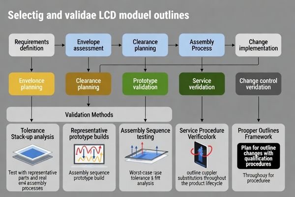
Custom integration succeeds when mechanical assumptions are tested as early as optical ones. The fastest path is to define the envelope clearly, budget realistic clearances, and then prove assembly and service with representative parts. If the module outline or mounting method can change over time, add change-control thinking upfront: define what measurements, trials, and inspections will be required to qualify substitutions without breaking fit across the product lifecycle.
Selection Methodology and Requirements Analysis
Envelope Assessment:
Systematic evaluation of module outline including all physical protrusions, connector locations, mounting features, and thickness stack to establish complete space requirements for integration planning.
Clearance Planning:
Development of realistic clearance targets based on tolerance stack-up analysis including module manufacturing variation, enclosure fabrication tolerances, gasket compression, and assembly process variation.
Constraint Mapping:
Identification of critical constraint relationships between outline dimensions and enclosure features including opening size, bracket positions, sealing interfaces, and adjacent component clearances.
Validation and Lifecycle Management
Prototype Verification6:
Representative build testing including actual bracket stiffness, gasket behavior, cable routing constraints, and service tool access to validate fit under realistic conditions rather than nominal CAD assumptions.
Assembly Process Validation:
Confirmation of assembly sequence feasibility including insertion forces, seating verification, fastening access, and extraction procedures under worst-case tolerance conditions with production-representative tooling.
Change Control Planning:
Development of qualification procedures for outline changes, supplier substitutions, or design modifications that maintain fit compatibility while enabling cost optimization and supply chain flexibility.
Inspection and Quality Control:
Establishment of measurement procedures and acceptance criteria ensuring production parts maintain interchangeability while identifying potential fit issues before assembly operations.
FAQ
Is outline dimension the same as active area?
No. Outline is the physical outer boundary used for mechanical fit, while active area is the pixel boundary used for optical alignment; both must be defined and referenced correctly.
Why can a module "fit" but still create stress or light leakage?
Because fit is not only about passing through an opening; seating flatness, gasket compression, and interference at corners or brackets can introduce stress and gaps.
What keep-out zones should I reserve around the outline?
Reserve space for connector backshells, cable bend radius, fastening tools, and any protrusions, and include tolerance and assembly variation in the keep-out definition.
How do I avoid "fits in CAD, fails in production"?
Use worst-case tolerance stack-up, include coatings and gasket compression, verify bracket stiffness and warp, and build representative prototypes before freezing tooling.
Do I need to control rotation as well as X/Y position?
Often yes—small angular errors can cause corner interference and uneven seating, so datum and locating features should constrain rotation.
When should I consider a custom outline?
When enclosure constraints, sealing strategy, connector routing, or service access leave little margin; a custom outline can reduce fit risk and simplify assembly.
Conclusion
Outline dimension represents the fundamental mechanical contract between LCD modules and enclosure systems, governing fit feasibility, assembly stress, and service accessibility through systematic dimensional coordination. Effective outline management requires treating physical envelope as the primary mechanical constraint while developing realistic clearance targets based on worst-case tolerance analysis and validation through representative prototype testing. By defining outline references systematically, validating fit under production conditions, and planning lifecycle change control procedures, teams avoid costly "fits on paper" failures while ensuring reliable assembly and service operations.
MEIDAYINGNUO provides comprehensive outline dimension analysis and mechanical integration services for custom LCD module applications requiring systematic fit validation, tolerance optimization, and assembly process development for complex enclosure constraints and service requirements. Our engineering team offers specialized expertise in mechanical design coordination, tolerance stack-up analysis, prototype validation methodology, and lifecycle management ensuring LCD modules achieve reliable mechanical integration while maintaining manufacturing feasibility and cost-effective production throughout extended deployment periods. Contact our mechanical integration specialists when outline dimension challenges require expert analysis and systematic validation support for successful custom integration projects.
✉️ info@lcdmodulepro.com
🌐 https://lcdmodulepro.com/
-
Learning to calculate worst-case tolerances is crucial for ensuring product reliability and performance. ↩
-
Understanding outline definition is crucial for ensuring proper fit and function in mechanical design, preventing costly errors. ↩
-
Exploring repeatable assembly techniques can enhance manufacturing efficiency and product quality, reducing errors and costs. ↩
-
Understanding datum strategy is crucial for ensuring precise assembly and fit in engineering projects. ↩
-
Discover the importance of service accessibility design for maintaining and servicing complex mechanical systems. ↩
-
Learn about the essential steps in prototype verification to ensure your designs meet real-world conditions and performance expectations. ↩