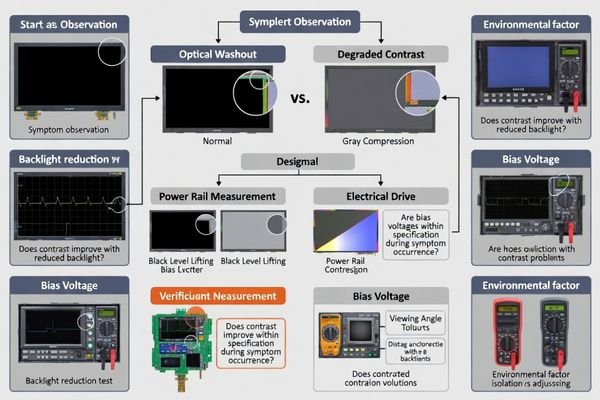
Sudden LCD contrast drops usually point to a shift in the module’s electro-optical operating point, not a simple content change. A practical troubleshooting flow isolates optical washout from electrical drive issues, then validates power, bias, firmware initialization, and environmental or mechanical triggers in a controlled, repeatable way.
A sudden contrast drop is usually caused by a shifted operating point: LCD bias/VOP or VCOM drifting, backlight or ambient conditions washing out the image, or viewing conditions leaving the designed window. Troubleshoot by isolating optical washout versus drive weakness, then verify rails/bias, initialization integrity, and environmental/mechanical contributors.
In many LCD display module integrations, “sudden” contrast issues come from marginal conditions that pass initial validation but fail under real stress—temperature swings, load transients, EMI/ESD events, or assembly pressure. The fastest path to a root cause is to keep the test method1 consistent: lock the content, control viewing angle and ambient light, and change only one variable at a time.
A reliable workflow separates what the user sees (washed-out blacks, compressed grays, angle sensitivity) from what the electronics are doing (bias and common voltage stability, timing integrity, and initialization completeness). Once you can reproduce the symptom on demand, you can confirm whether it tracks the host power/backlight system, the module’s bias generation, or the optical/mechanical stack.
What does a "sudden contrast drop" really indicate?
Sudden contrast drops typically represent electro-optical operating point shifts rather than content or brightness changes affecting display performance.
A sudden contrast drop usually means the LCD operating point moved: bias/VOP or VCOM shifted, temperature changed faster than compensation, or viewing/lighting conditions increased washout. First determine whether the LCD’s modulation weakened (bias/timing/temperature) or the image is being washed out (backlight/ambient/reflections), then test the relevant path.
From an engineering standpoint, the first decision is classification: did grayscale separation collapse electrically, or did the scene become optically harder to read? If blacks lift and mid-tones compress regardless of backlight changes, suspect bias and common voltage integrity, timing, or temperature effects. If readability improves when you reduce backlight or change angle/lighting, suspect washout driven by the optical stack and environment.
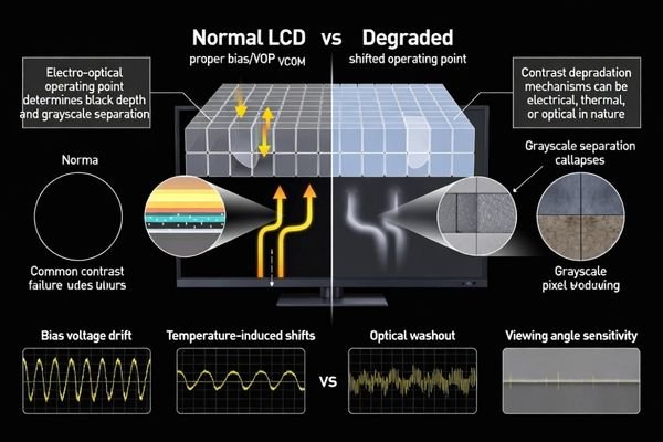
Electro-Optical Operating Point Shifts
LCD bias and common voltage establish the panel’s contrast “sweet spot.” If VOP (contrast/bias) or VCOM drifts due to supply sag, ripple, reference instability, or temperature effects, the grayscale response can flatten even while the display still updates normally. This often presents as reduced black depth, lower mid-tone separation, and a generally “milky” look that does not fully recover with backlight adjustment.
Optical Washout Versus Drive Weakness
Optical washout2 is a perception problem caused by veiling glare: too much backlight, strong ambient light, reflections from a cover lens, or a viewing angle outside the intended cone. The panel may be driven correctly, but the observer sees reduced contrast because the black level appears lifted by stray light. A quick indicator is that lowering backlight or shielding ambient light restores readability.
How do you quickly isolate power, bias voltage, and backlight effects?
Systematic isolation requires controlled testing separating optical washout from electrical drive problems through methodical parameter variation.
Run a fast A/B check: reduce backlight current and see if readability improves—if yes, suspect washout. If not, measure rails and bias at the moment of failure (VDD, any analog rail like VCI, and bias nodes such as VOP/VCOM/VGH/VGL as applicable). Small droop or ripple can flatten grayscale even without a blackout.
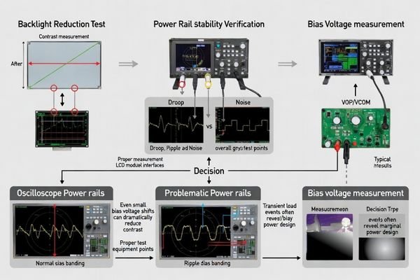
Keep the content fixed and avoid changing multiple knobs at once. Start by stepping backlight brightness in a controlled way and logging the observer result. If contrast tracks backlight strongly, focus on the backlight driver3, PWM artifacts, ambient light, and optical reflections.
If contrast does not recover when backlight is reduced, shift to electrical verification under the exact load and timing when the symptom appears. Measure logic supply stability and any generated bias rails relevant to your module architecture. Pay attention to transient dips, ripple increases, or ground bounce during CPU load changes, radio bursts, or motor starts. If a booster/charge pump is involved, confirm headroom and decoupling quality, because marginal capacitors can pass bench tests but fail under aging, temperature, or vibration.
Which software and timing checks catch "contrast changed" after reboot or ESD?
Software and timing validation focuses on initialization completeness and register integrity following system events affecting display parameters.
If contrast changes after reboot, sleep/wake, brownout, or ESD, suspect incomplete initialization or corrupted registers. Verify reset sequencing and required delays, and ensure the full configuration set (gamma, VCOM, bias level, pixel format) always loads in the correct order. Validate bus integrity, because a few bit errors can flatten gamma without stopping refresh.
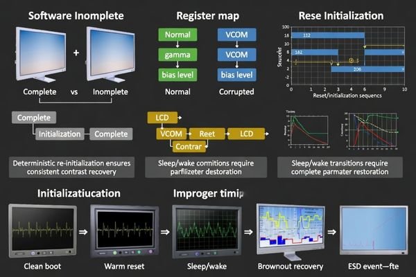
Many “post-event” contrast problems are repeatable once you treat them as state issues. Confirm that warm resets do not skip display-parameter writes, and that undervoltage conditions cannot leave the controller half-initialized. If your platform can read back critical settings, compare register states between “good” and “bad” conditions. If not, treat the display configuration as non-persistent and enforce a deterministic re-initialization sequence after any event that could disrupt state (watchdog resets, brownout recovery, ESD indicators, or sleep/wake transitions).
| Event Type | Common Failure Mode | Diagnostic Approach |
|---|---|---|
| System Reboot | Incomplete initialization sequence | Verify full command list execution |
| Sleep/Wake Cycles | Partial register restoration | Validate complete parameter reload |
| ESD Events | Register corruption | Compare good vs bad register maps |
| Brownout Recovery | Half-initialized controller state | Implement robust reset sequencing |
A practical safeguard is to define a “known-good display state4” and always restore it when system integrity is questionable. This turns intermittent, hard-to-diagnose contrast changes into a controlled recovery behavior.
What environmental and mechanical factors can suddenly reduce LCD contrast?
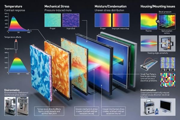
Environmental and mechanical factors can create sudden contrast changes through temperature effects, optical interference, and mechanical stress on display components.
Rapid temperature changes can shift LCD response and the optimal bias point, lifting blacks and compressing mid-tones without any firmware change. Moisture or condensation can add scattering and mimic contrast loss. Mechanical pressure, torque, or uneven adhesive stress can disturb the optical stack, causing mura and reduced effective contrast—especially after assembly changes or thermal cycling.
To isolate these factors, control the environment: reproduce the issue at a fixed temperature and then step temperature deliberately while observing the same test pattern. If contrast degradation correlates strongly with temperature, review whether compensation assumptions match your real operating range. For moisture-related issues, look for fogging, residue, or changes after humidity exposure.
Mechanical and optical stack effects often show up as angle sensitivity, localized mura, or improvement when the module is tested outside the enclosure. Compare in-housing versus out-of-housing behavior under identical backlight and ambient conditions. If contrast improves out of housing, investigate bezel pressure on the active area, mounting torque, adhesive thickness uniformity, light leakage, and reflections introduced by a cover lens or touch stack.
Temperature-Related Contrast Shifts5
Temperature alters liquid crystal viscosity and response, which shifts the best operating point for contrast. Without matching compensation, blacks may lift and gray separation may compress during rapid ambient changes or when operating near the edges of the intended temperature window. A controlled temperature sweep with fixed electrical settings is one of the fastest ways to confirm a temperature-driven mechanism.
Mechanical Stress and Optical Stack Effects
Assembly pressure and uneven stress can change optical behavior, creating mura and reducing perceived contrast even when electrical drive is stable. Optical additions—cover lenses, coatings, touch panels, diffusers—can increase veiling glare and reflections, washing out the image under real lighting. Testing the module outside the enclosure and under different ambient light angles helps separate electrical root causes from optical/mechanical ones.
How can you prevent repeat contrast drops with a robust troubleshooting playbook and design rules?
Prevention requires systematic playbooks combining diagnostic procedures, design safeguards, and validation protocols addressing all potential contrast degradation mechanisms.
Prevent repeat contrast drops by standardizing a playbook: define a known-good reference state (rails, bias, backlight, temperature, viewing angle) and require logging when reproducing failures. Add safeguards—rail monitoring, controlled sequencing, and deterministic re-initialization after brownout/ESD/sleep-wake—so the module cannot silently drift into a low-contrast state.
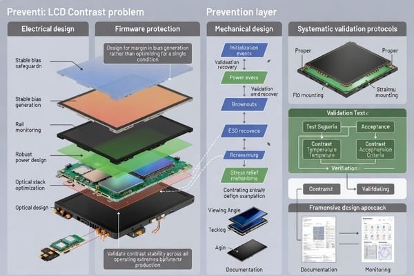
A prevention strategy works best when it turns “contrast” into measurable variables and repeatable actions. Electrically, prioritize stable bias generation with adequate rail margins, low-noise regulation, and disciplined decoupling/grounding to reduce transient shifts that compress grayscale. Firmware should treat display configuration as a controlled state machine: verified reset timing, complete parameter loads, and a clear recovery path after any integrity event.
Optically and mechanically, treat the display stack as part of the system design. Avoid pressure on the active area, control adhesive thickness and mounting torque, and qualify cover lens/touch stacks for reflection and glare under real ambient lighting. Finally, validate contrast stability6 in reliability testing (temperature cycling, vibration, ESD/EMI exposure, aging) so you can detect drift early and lock in robust design rules.
Electrical Design Safeguards
Power System Stability: Use rail monitoring for undervoltage and excessive ripple, maintain bias generation headroom, apply disciplined sequencing to avoid partial states, and ensure decoupling and grounding reduce transient shifts that flatten gamma or lift blacks.
Register Protection: Where possible, validate critical configuration writes and enforce deterministic re-initialization after watchdog resets, brownout recovery, ESD indicators, or repeated interface errors. Confirm initialization delays across temperature so the same command list produces the same operating point.
Optical and Mechanical Prevention
Assembly Control: Define build rules that prevent pressure on the active area, control adhesive thickness and uniformity, and specify mounting torque to avoid warpage. Include checks for light leakage paths that can raise perceived black level.
Environmental Qualification: Validate contrast across the full operating temperature range, qualify optical stack additions (cover lens/touch) for reflection control, and define viewing angle and ambient lighting expectations to reduce washout risk. Add moisture mitigation where condensation is plausible.
Validation and Monitoring Framework
Systematic Testing: Include contrast verification in reliability plans (temperature cycling, vibration, ESD/EMI, aging). Define acceptance criteria for contrast stability and monitor batch-to-batch consistency so changes in components or process do not introduce drift.
Documentation and Continuous Improvement: Keep troubleshooting logs that connect symptoms, measurements, root causes, and fixes. Convert recurring findings into design rules and checklists so future projects avoid the same contrast failure modes.
FAQ
Is a contrast drop more likely caused by LCD bias or backlight settings?
If lowering backlight brightness improves readability, it often indicates washout; if grayscale separation stays poor regardless, prioritize checking bias/VOP, VCOM, and rail integrity.
What’s the single fastest test to run on the bench?
Reproduce the issue with a stable lab supply and fixed backlight current; if the problem disappears, it likely originates in the host power/backlight driver rather than the module.
Why can contrast drop after sleep/wake even when the image still refreshes?
A partial initialization or corrupted registers can leave gamma/VCOM/bias values wrong while refresh continues; a full re-init on wake is a common fix.
Can temperature changes cause an abrupt contrast shift?
Yes—rapid ambient changes shift response and optimal bias; without compensation, blacks lift and mid-tones compress, especially outside the designed temperature window.
How do I know if mechanical stress is involved?
Compare behavior inside vs outside the enclosure; if contrast improves out of housing, investigate bezel pressure, torque, adhesive stress, and light leakage paths.
What prevents register corruption from turning into a field issue?
Brownout detection, robust reset sequencing, validated init delays, and a watchdog-triggered deterministic re-init that restores known-good display parameters.
Conclusion
Troubleshooting sudden LCD display module contrast decreases works best when you first separate optical washout from true electro-optical shifts, then verify power/bias stability, initialization robustness, and environmental or mechanical triggers under controlled conditions. A repeatable playbook—consistent logging, deterministic recovery routines, disciplined bias and power design, and optical/mechanical qualification—turns intermittent contrast complaints into measurable causes and reliable fixes.
MEIDAYINGNUO provides LCD display module engineering support for contrast stability challenges, including power and bias analysis, initialization and timing reviews, environmental/mechanical root cause isolation, and validation planning for reliable long-term readability. Contact our technical specialists when contrast stability issues require structured diagnostics and design-rule hardening for demanding operating conditions.
✉️ info@lcdmodulepro.com
🌐 https://lcdmodulepro.com/
-
A consistent test method is crucial for accurate diagnostics and ensuring reliable performance in LCD integrations. ↩
-
Exploring the causes of optical washout can help improve viewing experiences and enhance display clarity. ↩
-
Understanding backlight drivers is crucial for troubleshooting display issues, ensuring optimal performance and longevity. ↩
-
Defining a known-good display state is crucial for ensuring system integrity and preventing display issues. ↩
-
Understanding temperature’s impact on contrast shifts can help optimize display performance and enhance visual quality. ↩
-
Understanding contrast stability is crucial for ensuring high-quality display performance and longevity. ↩