Rail carriage information display selection requires specialized bar module evaluation that fits the carriage layout, stays readable in real lighting, and survives the vibration/EMI/lifecycle realities of rail service.
In rail carriages, a bar module isn’t “just a wide screen.” It’s part of a long-life information system that must stay readable from awkward angles, stay stable under vibration and EMI, and remain serviceable and consistent across years of maintenance and revisions.
In my LCD display module integration work at LCD Module Pro, I’ve learned that rail carriage projects are won (or lost) in the details people often skip in normal signage: real viewing angles, interconnect robustness under motion, and lifecycle discipline. When I help teams choose a bar module, I try to keep it practical: start from where the module actually sits in the carriage, define what “readable” really means under cabin light and window glare, then validate stability and durability the way the train will actually use it.
What makes rail carriage information displays different from typical digital signage?
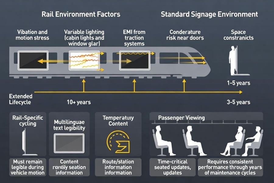
Rail carriage displays operate under specialized environmental conditions, content requirements, and lifecycle constraints that distinguish them from conventional digital signage applications.
Rail carriage information displays operate in vibration-rich, temperature-variable, high-EMI environments where readability and reliability matter more than cosmetic perfection. Content is often text-dominant, multi-language, and time-sensitive, so legibility from multiple angles and stable refresh behavior are critical. Unlike retail signage, rail systems run long service lifecycles with planned maintenance windows and strict change control, so selection must consider supply continuity, revision stability, and field replaceability. Space is constrained by carriage architecture, which is why ultra-wide bar modules fit naturally above doors or along panels without blocking sightlines.
Based on the projects I support with rail transportation display integration, the biggest difference is that the “environment” isn’t just temperature—it’s a stack of stresses happening at once. The module has to remain legible during motion, remain stable through daily power cycling, and stay consistent after years of maintenance-driven handling. That’s why I treat rail selection as a system decision: optics, mechanics, signal chain, and lifecycle planning all matter at the same time.
Environmental and Operational Challenges
Rail carriage environments present continuous vibration, temperature cycling, electromagnetic interference, and condensation risks that demand robust mechanical design and reliable electronic operation while maintaining consistent display performance throughout daily operational cycles and seasonal environmental variations.
Content and Lifecycle Requirements
Transportation information systems must deliver time-critical, multilingual content with high legibility standards while supporting extended service lifecycles, planned maintenance schedules, and strict configuration control ensuring reliable operation throughout multi-year deployment periods with minimal service interruption.
Which optical targets ensure readability under carriage lighting and passenger viewing angles?
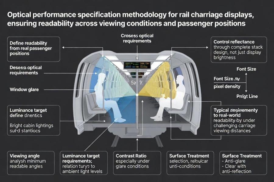
Optical specification development requires systematic analysis of carriage viewing geometry, ambient lighting conditions, and passenger interaction patterns to ensure consistent readability performance.
Start from real viewing geometry—standing and seated distances, typical tilt angles, and glare sources from cabin lights and windows. Set luminance targets with margin so text stays readable under bright cabin lighting and near-window daylight, and control reflectance through the cover-lens and surface-treatment strategy at the stack level. Verify wide viewing angle behavior for text contrast and color shift, because passengers read from oblique angles and the content must remain crisp. Finally, match pixel density to viewing distance: too low softens characters, while too high can make grain/sparkle more noticeable if the stack uses aggressive anti-glare.
From an engineering standpoint, I always remind teams that “more brightness” isn’t the whole story in a carriage. If reflections aren’t controlled, you can raise luminance and still end up with washed-out text near windows. For text-heavy information displays, perceived contrast and black-level retention under glare often drive passenger satisfaction more than peak luminance alone, so the optical targets should be written around readability outcomes, not only a single number.
How do you select interface, timing, and signal-chain design for stable operation?
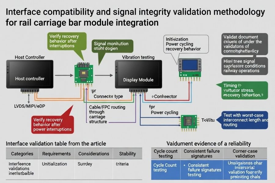
Interface selection requires comprehensive compatibility validation addressing electrical performance, timing stability, and signal integrity under transportation-specific environmental stresses and interconnect constraints.
Compatibility is more than the interface name. You need to align the host output format, margin at the chosen rate, and the module’s initialization and recovery behavior with what your system actually does in the carriage. Long bar modules amplify interconnect and EMI sensitivity: cable/FPC length, grounding, and connector robustness can turn a stable bench setup into intermittent field dropouts. I treat power sequencing, reset behavior, and sleep/wake recovery as part of the interface contract, then validate at worst-case timing and temperature corners. Just as important, I require evidence—cycle counts, pass rates, and consistent failure signatures—so the team can reproduce problems and avoid “it passed once” decisions.
When I troubleshoot interface stability issues in transportation environments, the root cause is often not the “protocol” but the margin around it—especially what happens during transitions (boot, power cycling, wake) when vibration and EMI are present. A stable rail design is one that keeps working when the interconnect flexes slightly, when the supply ramps a bit slower in winter, and when the system recovers from brief disturbances without manual intervention.
| Interface Category | Validation Requirements | Transportation Considerations | Stability Criteria |
|---|---|---|---|
| Electrical Compatibility | Host-module alignment, margin verification | EMI coupling, power cycling behavior | Consistent initialization across temperature |
| Interconnect Integrity | Cable/FPC length, connector robustness | Vibration stress, mechanical flexing | No intermittent dropouts under motion |
| Timing Stability | Worst-case corner validation | Temperature cycling, supply tolerance | Reliable wake/sleep transitions |
| Signal Quality | Signal margin and robustness assessment | EMI interference, grounding effectiveness | Error-free operation with diagnostic capability |
| Recovery Behavior | Power sequencing, reset handling | System cycling, fault recovery | Predictable startup without manual intervention |
Systematic interface validation keeps the signal chain stable across carriage operating cycles and makes field troubleshooting faster because the team already knows what “normal” looks like, what corner cases were covered, and what failure signatures to look for.
What mechanical, environmental, and reliability validations reduce rail field failures?
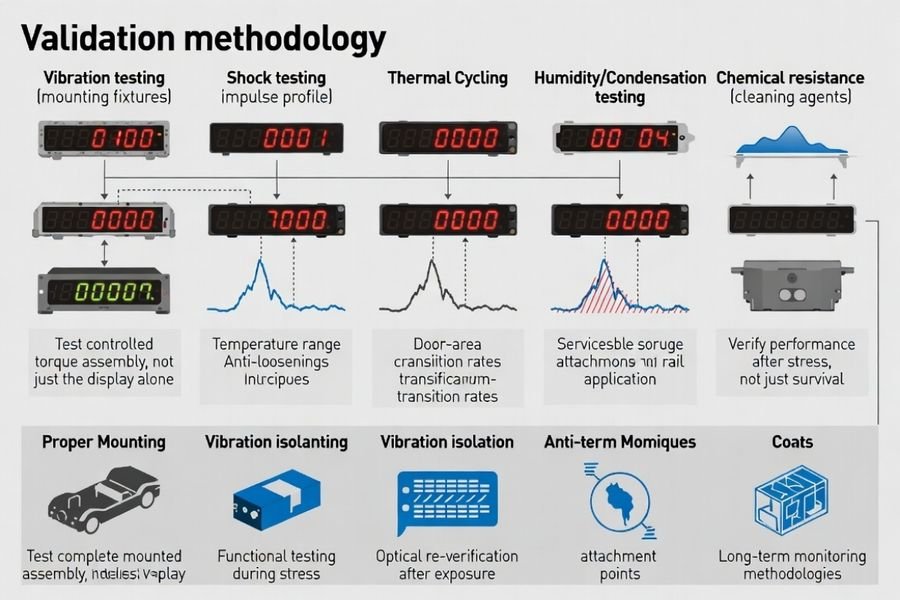
Comprehensive validation methodology addresses transportation-specific stress factors including vibration, thermal cycling, and chemical exposure ensuring long-term reliability and consistent performance.
Bar modules in rail carriages must survive vibration, shock, and long-term thermal cycling without connector fretting, frame warpage, or optical stack drift. Define mechanical mounting with controlled torque, anti-loosening strategy, and vibration-isolated supports so the module is not stressed by enclosure flex. Environmental validation should match carriage reality: temperature/humidity cycling, door-area condensation risk, and cleaning chemical exposure from maintenance. Finally, verify robustness against EMI/ESD events common in rail systems and tie pass/fail to functional stability and post-stress optical re-checks, not just “no visible damage.”
I’ve seen plenty of “looks fine on the bench” modules fail after months in service because the mounting and interconnect weren’t treated as reliability-critical. In rail, small mechanical issues can snowball: connector micro-motion can create intermittent flicker, enclosure flex can introduce edge stress, and door-area humidity swings can accelerate corrosion or contact instability. The validation that matters most is the kind that forces these issues to show up early—then confirms the display still meets readability and stability expectations after stress, not only that it didn’t crack.
Mechanical Stress and Mounting Validation
Vibration and Shock Resistance:
Systematic testing under railway vibration profiles including frequency sweeps, shock pulses, and long-term fatigue validation ensuring mechanical integrity, connector stability, and optical performance consistency throughout operational lifecycle without degradation or intermittent failures.
Mounting System Optimization:
Controlled torque specifications, anti-loosening strategies, and vibration isolation techniques preventing module stress from enclosure flexing while maintaining secure attachment and thermal interface integrity throughout temperature cycling and mechanical stress exposure.
Environmental Durability and Chemical Resistance
Temperature and Humidity Cycling:
Comprehensive thermal validation including condensation resistance, sealing effectiveness, and performance stability across railway operating temperature ranges ensuring reliable operation in door-area environments and seasonal climate variations.
Chemical Exposure and Cleaning Validation:
Testing against railway maintenance chemicals, cleaning procedures, and surface treatment durability ensuring optical stack integrity and performance consistency throughout extended service lifecycles and routine maintenance protocols.
How to select the right bar-type LCD module solution for rail carriage information displays?
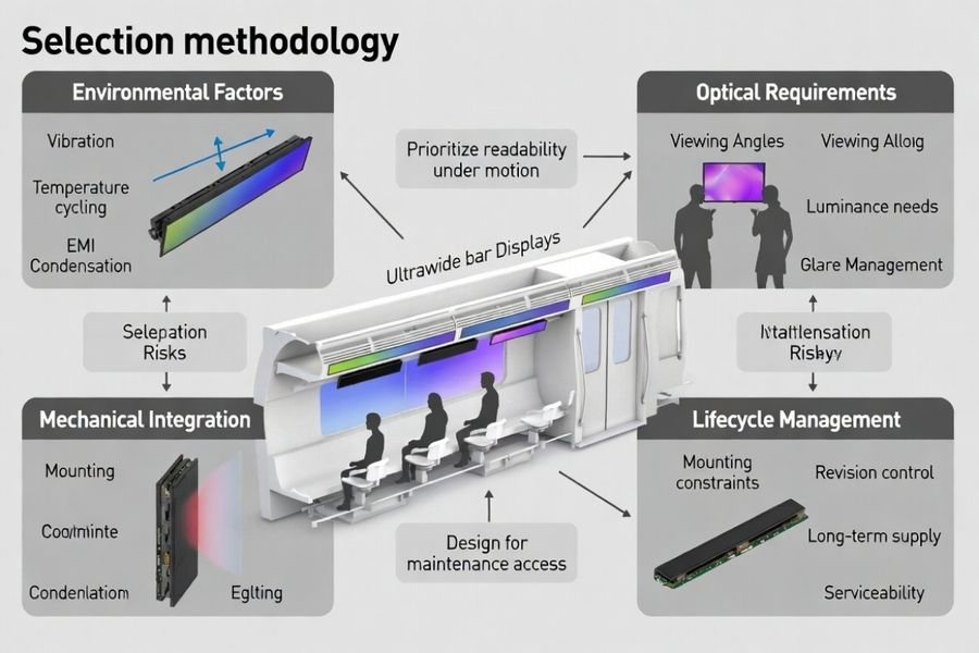
Bar module selection requires systematic evaluation of installation constraints, performance requirements, interface compatibility, and lifecycle management ensuring optimal carriage information display integration.
Selection methodology should progress systematically through installation analysis, performance optimization, compatibility validation, and serviceability planning to achieve reliable rail carriage information display implementation.
Installation Analysis and Performance Optimization
Carriage Integration Assessment:
Evaluate installation envelope, mounting zone dimensions, and viewing geometry requirements selecting bar module size and aspect ratio that fits carriage architecture while maintaining text legibility at real passenger viewing distances and angles throughout carriage layout and seating configurations.
Optical Performance Balancing:
Balance resolution and pixel density against content requirements and font scaling ensuring multilingual route and station information remains crisp while coordinating brightness levels, cover lens selection, and anti-reflection strategies controlling glare without reducing contrast or introducing optical artifacts.
Interface Compatibility and Signal Chain Validation
Host Platform Integration:
Confirm interface and timing compatibility including wake and sleep behavior, recovery procedures, and initialization sequences ensuring reliable communication between host controller and bar module throughout power cycling and system state transitions common in carriage operations.
Signal Integrity Optimization:
Validate complete signal chain under worst-case interconnect conditions and EMI environments including cable length effects, grounding effectiveness, and connector reliability ensuring stable operation throughout carriage electromagnetic environment and mechanical stress exposure.
Lifecycle Management and Serviceability Planning
Configuration Control and Supply Continuity:
Lock validated configuration including revision control requirements, change notification procedures, and reference sample maintenance ensuring consistent performance characteristics throughout production lifecycle while preventing unexpected compatibility changes or supply disruptions.
Field Service and Replacement Strategy:
Plan serviceable mounting procedures, consistent mechanical references, and replacement protocols enabling efficient field maintenance while ensuring supply continuity and avoiding disruptive end-of-life transitions that could impact railway operational schedules.
FAQ
Are bar modules always better than standard rectangular modules for rail carriages?
Not always. Bar modules fit narrow mounting zones well, but the best choice depends on the available space, viewing distance, content layout, and how the enclosure manages glare and heat.
How bright does a carriage information display need to be?
It depends on cabin lighting and window exposure. Define a luminance target with margin for near-window daylight and consider reflectance control from the cover lens and surface treatment to protect readability.
What’s the biggest risk to MIPI/LVDS/eDP stability in long bar displays?
Interconnect margin. Cable/FPC length, grounding, connector robustness, and EMI coupling can turn a stable bench setup into an intermittent field failure if not validated at worst-case conditions.
How do you prevent vibration from causing intermittent flicker or dropouts?
Control mounting torque, use anti-loosening design, secure the interconnect, and validate under vibration profiles while monitoring for flicker, link errors, and recovery behavior.
Should you validate condensation and cleaning chemicals for carriage displays?
Yes. Door-area condensation and maintenance cleaners can damage optical stacks and coatings, so chemical and humidity/temperature validation should match real service practices.
How do you manage long lifecycle and replacement risk for rail display modules?
Lock a validated configuration, require change notification, keep reference samples, and plan serviceable mounting and supply continuity to reduce EOL disruption.
Conclusion
Choosing bar modules for rail carriage information displays requires systematic matching of the installation envelope and viewing geometry to the right ultra-wide format, followed by validation of readability, signal stability, and durability under rail-specific vibration, thermal cycling, condensation risk, and EMI conditions. In my experience, the teams that succeed are the ones that treat the interface contract (including power sequencing and recovery) and the maintenance reality (serviceability, revision control, and supply continuity) as first-class design inputs—not afterthoughts. When those pieces are planned early, field failures drop and the passenger experience stays consistent across long deployments.
LCD Module Pro provides specialized bar module selection and validation services for rail carriage information display applications requiring transportation-specific environmental testing, signal integrity optimization, and lifecycle management across demanding railway operational requirements and extended service conditions. Our engineering team offers expert guidance in railway display integration methodology, vibration and EMI testing protocols, interface validation procedures, and serviceability planning ensuring bar-type LCD modules deliver reliable information display performance while maintaining mechanical integrity and operational consistency throughout extended railway service lifecycles and environmental stress exposure.
✉️ info@lcdmodulepro.com
🌐 https://lcdmodulepro.com/