Field issues with LCD modules can create costly warranty claims and damage brand reputation. Yet many common failures could be prevented through proper system-level validation during the design phase. The fastest way to reduce risk is to define a design-stage validation plan that uses real harness length/routing, real power ripple, active RF sources, temperature/humidity stress, repeated power cycling, ESD, and vibration—because these are the conditions that often turn “works on the bench” into “fails in the field.”
The most impactful field problems are rarely complete display failures, but rather intermittent issues that emerge over time: display flicker, touch inconsistency, accelerated brightness decay, and environment-triggered glitches. Success requires shifting from basic functional testing to comprehensive system validation during design.

In field investigations across different device types, most issues trace back to reduced margins1 across multiple subsystems. The display may work perfectly on the bench with short cables, yet develop problems in real deployments where thermal stress, EMI, and mechanical strain combine to expose design weaknesses. The design-stage goal is to make worst-case conditions real early, and to add the debug hooks that turn “random” failures into reproducible events before tooling and harness designs are frozen.
What Are the Most Common LCD Module Field Problems and Where Do They Usually Come From?
Understanding failure patterns is the first step toward prevention through design.
Field issues typically cluster around four key areas: optical degradation (brightness decay, poor sunlight readability), signal integrity problems (flicker, artifacts, black screens), environmental stress effects (condensation, temperature sensitivity), and mechanical-electrical intermittents in connectors and harnesses.

Let’s examine how these problems manifest in real deployments: flicker or artifacts often appear during cold start2, during radio transmit bursts, when backlight PWM changes, or after a door/panel is opened and the harness is disturbed. Condensation-related issues tend to show up after night-time cooling, during rapid temperature swings, or in sealed enclosures where moisture accumulates. If you can name a trigger condition, you can design a test to reproduce it—and once it’s reproducible, it’s fixable.
Physical Failure Patterns
Most issues develop gradually through combined stress effects rather than sudden catastrophic failures. Intermittents commonly worsen over time as vibration, repeated servicing, and thermal cycling reduce connector retention, increase contact resistance, or change shielding/ground contact quality. Optical complaints also often evolve: glare becomes more noticeable as covers scratch or accumulate residue, and brightness decay becomes obvious once the product is used at higher brightness for longer than expected.
Root Cause Distribution
Problems often cross boundaries between optical design, thermal management, signal integrity, and mechanical assembly—requiring system-level solutions. A “display problem” might be a power-rail transient, a harness return-path issue, an EMI coupling path, or a mechanical stress point. The most effective teams treat the display as a subsystem spanning optics, mechanics, power, and high-speed signaling, and design margin across all of them.
How Can You Surface and Eliminate Intermittent LCD Issues During the Design Stage?
Catching intermittent issues early requires moving beyond basic functional testing.
Successful prevention of field issues demands three key design-stage actions: implementing system-level stress testing that reflects real deployment conditions, adding sufficient debug hooks and monitoring points, and validating the complete assembly under boundary conditions before design freeze.
Test Environment Enhancement
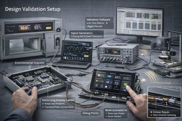
Create conditions that expose margin problems: long cables, real power supplies, RF sources, thermal stress, and mechanical strain—don’t rely on bench-top demonstrations. A practical stress matrix is to vary temperature, harness length/routing, RF transmit activity, power ripple/load transients, backlight PWM levels, and mechanical disturbance (vibration/door movement), then run long-duration tests plus repeated power-cycling. If a failure only happens in the field, your lab conditions are usually missing one of the triggers or the combined trigger sequence.
Debug Infrastructure
Design in test points, logging capabilities, and fault injection methods3 that make intermittent issues reproducible and diagnosable. Add access to key rails (logic and backlight), critical signals, and ground references; capture boot/wake timing and display init states; and define repeatable fault injection such as enabling radio bursts, stepping PWM duty cycles, toggling power sequencing, and gently disturbing the harness. The goal is to shorten the “time to reproduce” so root cause can be isolated before design freeze.
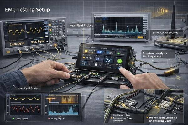
How Do You Prevent Flicker, Artifacts, and Black Screens Through Interface, Harness, and EMI/EMC Design?
Signal integrity issues often emerge only after system integration.
Display stability depends on maintaining adequate signal margin across three domains: the interface must have sufficient bandwidth and noise immunity, the harness design must control EMI coupling and ground loops, and the power delivery must remain clean under all operating modes.
| Issue Area | Common Causes | Design Controls | Validation Methods | Success Criteria |
|---|---|---|---|---|
| Signal Integrity | Cable Length/Quality | Interface Selection | Real Harness Testing | No Artifacts under stress matrix |
| Power Quality4 | Rail Noise/Ripple | Filtering Design | Load Transient Tests | Stable rails during start/wake/PWM steps |
| EMI/EMC | Ground Loops/Coupling | Shield/Ground Strategy | Pre-compliance Tests | Pass pre-compliance with margin |
| Mechanical | Connector Stress | Strain Relief | Stress Testing | No intermittents after cycling |
If cables are long, routed near noisy power sections, or the device includes radios, treat SI/EMC validation as a gating item before harness and enclosure designs are frozen. Preventive design controls typically include: clear return paths, consistent shield termination strategy, separation from high dV/dt nodes, connector retention/strain relief, and power sequencing that avoids brownouts during wake or brightness transitions. Many “random black screens” are actually power integrity or init-timing problems triggered by load transients, not a panel defect.
How Can You Control Brightness Decay, Heat, Condensation, and Outdoor Aging During Design?
Long-term reliability requires managing environmental stress from day one.
The key to preventing premature aging lies in controlling four interactive factors: thermal management must handle both internal heat and environmental loads, brightness strategy must balance visibility against lifetime, moisture protection must prevent condensation cycles, and material choices must withstand real-world aging.
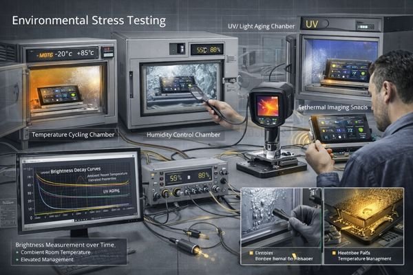
Thermal Design Strategy
Think beyond typical conditions—validate performance under worst-case heat loads and cycling. Define acceptance-ready targets such as allowable temperature rise at your normal brightness profile, and verify cabinet hot spots under worst ambient and worst internal loading. If your product runs 24/7 or at high brightness for long periods, thermal margin and brightness strategy5 become the primary levers that determine backlight aging behavior.
Lifetime Management
Define clear end-of-life criteria and verify your design provides adequate margin through accelerated testing. Practical lifetime definitions combine hours/day, ambient temperature range, target brightness, and acceptable EOL brightness/color shift. Pair this with real-world dimming strategy (day/night profiles, wake-on-demand, limits on maximum duty) and validate using long-run aging plus temperature-humidity cycling while powered on. For condensation risk, identify cold spots and moisture paths early, then validate with powered temperature-humidity cycling because condensation-related failures often require both moisture and electrical bias to appear.
Recommended MEIDAYINGNUO Models to Shortlist
Our experience has identified display solutions that consistently demonstrate robust field performance.
Our engineering team specializes in helping customers validate complete system solutions against real-world conditions.
| Field Challenge | Performance Needs | Environment | Recommended Model | Design Considerations |
|---|---|---|---|---|
| Outdoor Readability | High Brightness | Full Sun | HB238X | Thermal Management |
| Indoor Reliability | Touch Stability | Climate Control | SQ220S | EMI Protection |
| Status Display | Always-On | Mixed Light | BU215X | Power Strategy |
| Sunlight + Heat | Optical Clarity | High Ambient | HB215X | Stack Design |
| Premium Indoor | Indoor UI Layout | Controlled | SQ332S | Interface Protection |
Treat these models as a shortlist rather than a drop-in guarantee. Final matching should be confirmed through your actual optical stack, thermal behavior at required brightness, harness routing/length, EMC pre-validation, and end-of-life brightness targets. If the deployment involves long cables, strong EMI, sealed enclosures with humidity cycling, or 24/7 high brightness, system-level validation is the deciding factor—not the datasheet headline specs.
FAQ
How do you identify signal margin problems before production?
Test with real harness lengths and routing, actual power supplies, and RF sources operating. Monitor margins across temperature, and include power-cycling and backlight PWM steps—if long cable + noise is your reality, your validation must replicate it.
What causes accelerated brightness decay in the field?
Usually combination of thermal stress and high-duty operation. Define EOL brightness targets, design cooling paths, and implement smart brightness control (day/night profiles, limits) so the backlight isn’t continuously operated at maximum stress.
Why do touch panels become erratic over time?
Often due to moisture ingress, thermal cycling, or EMI sensitivity. Validate sealing and materials, and test touch stability with radios active, wet fingers, and cleaning residue under temperature-humidity cycling.
How can you prevent connector-related intermittents?
Design proper strain relief, use appropriate retention, and validate under vibration and thermal cycling. Many “display faults” are harness/connector intermittents triggered by repeated service or door movement.
What’s the best way to make field issues reproducible?
Add test points and monitoring during design, then build a stress matrix (temperature × harness × RF × power ripple × PWM × mechanical disturbance) and run long-duration plus repeated power cycles until triggers are repeatable.
Conclusion
Preventing LCD field issues requires comprehensive system validation during design. By understanding failure modes and implementing thorough testing before design freeze, device makers can reduce field problems and support costs while improving product reliability.
MEIDAYINGNUO specializes in helping customers validate display solutions against real-world conditions. Our team can help identify and eliminate potential field issues during the design phase. For detailed discussion of your system requirements, please contact our engineering team.
✉️ 961531917@qq.com
🌐 https://lcdmodulepro.com
-
Understanding reduced margins can help improve device reliability and performance in real-world conditions. ↩
-
Understanding cold start effects can help in designing better systems and mitigating issues during deployment. ↩
-
Exploring fault injection methods can enhance your debugging process, making intermittent issues easier to reproduce and diagnose. ↩
-
Improving power quality is essential for stable operation and can help avoid issues like brownouts and system failures. ↩
-
Understanding this strategy is crucial for optimizing product performance and longevity, especially in high-demand environments. ↩