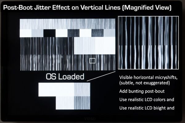
One of the most challenging issues an engineer can face is an LCD display module that looks perfect during the initial boot sequence, only to start jittering once the main operating system loads. This post-boot instability is frustrating because it often comes from hardware signals that change because software changes system clock and power policies after boot.
To diagnose clock instability behind post-boot image jitter, first confirm the motion is clock-like (continuous shimmer or micro-shifts on fine vertical edges). Then correlate the onset with post-boot events (driver load, SSC/DVFS enable, clock-tree switching). Finally, measure pixel clock stability and related supply rails at the display connector and prove causality with controlled A/B experiments (lock/disable SSC or DVFS, change reference source, vary load and temperature).
In LCD Module Pro customer integrations, this pattern commonly appears when the clocking or power-management policy changes after the bootloader stage. A bootloader may use a simple, stable clock configuration, but the OS display stack can enable spread-spectrum clocking (SSC) for EMI reduction, dynamic voltage and frequency scaling (DVFS)1 for power, or different PLL settings for mode management. If the receiver margin is tight—or if the PLL supplies and references are noisy—those post-boot changes can translate into visible pixel-clock phase noise.
The fastest way to solve the problem is to stop guessing and make the behavior measurable. Treat “jitter after boot” as a state-transition problem: identify exactly when it starts, measure what changes at the connector, and then change only one variable at a time until the jitter follows that variable.
What jitter patterns suggest clock instability versus other display faults?
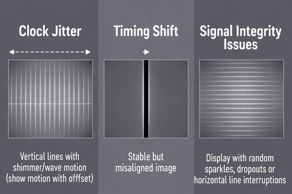
The first step in any diagnosis is to correctly identify the visual signature. Clock instability looks different from timing shifts and signal-integrity failures.
Clock instability typically looks like continuous horizontal shimmer, micro-shifts, or “twitching” of vertical lines and sharp edges. It is dynamic motion that may change with temperature, time, or system load—unlike timing errors that create stable geometric offsets, or SI faults that create sparkles, line dropouts, or intermittent loss of sync.
A disciplined visual check can narrow the search quickly—especially if you use patterns that amplify the effect.
The Signature of Clock Jitter
Clock jitter is phase noise: clock edges don’t arrive at perfectly regular intervals. The receiver samples video slightly early or late, which shows up as a subtle but persistent wobble or shimmer. It is easiest to see on high-contrast vertical lines, sharp text, or checkerboard patterns, and it may include a periodic twitch component if the jitter is being modulated by a repeating system activity.
Differentiating from Other Faults
Timing parameter mismatch (for example, wrong porch values) causes stable shift or cropping with fixed black bars—movement is not continuous. Signal integrity problems2 are often more erratic: random sparkles, transient line errors, or dropouts, and they can worsen with cable movement or EMI changes. If what you see is continuous micro-motion on fine edges, keep clock stability high on the suspect list. Next step: correlate the onset to post-boot state changes.
Which clock sources in the display chain most commonly destabilize after boot?
If jitter begins only after the OS loads, the most likely culprit is a clock domain that the OS reconfigures. Map the clock path end-to-end.
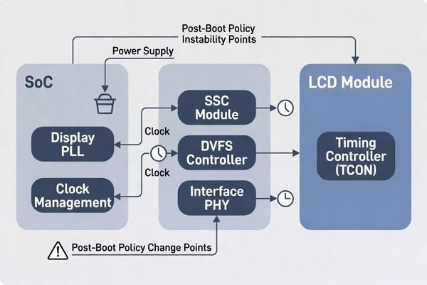
Post-boot instability most often originates in the host SoC’s display PLL (pixel clock), a PHY/link clock domain (for serialized interfaces), or a reference clock feeding a bridge/scaler. OS-driven changes such as enabling SSC, DVFS, or switching clock trees after boot are frequent triggers—especially when PLL supplies or ground references are noisy.
In most systems, the LCD module is the victim: it can only display what the clock allows it to sample.
- Pixel clock PLL (SoC display PLL)3: The OS driver may reprogram the PLL after boot, adjust dividers, enable SSC, or change mode policies. Marginal PLL settings or noisy PLL rails can increase phase noise.
- Interface PHY clock (e.g., serializer clock domains): Even if the UI looks “pixel-clock-like,” instability can originate upstream where the interface clocking is re-locked or retimed.
- Bridge/scaler reference clock: Bridge chips depend on a stable reference. Some platforms switch from a stable crystal used at boot to an SoC-derived reference after the OS loads, which can change jitter performance.
Next step: isolate whether the jitter follows clock policy changes (SSC/DVFS/PLL settings) or follows load/power noise.
How do you isolate clock instability from power noise, timing errors, or cable issues?
Isolation works best when you change only one domain at a time while keeping everything else fixed.
Isolate clock instability with A/B tests: keep the video mode and timing fixed while toggling clock policies (disable SSC, lock PLL settings, disable DVFS, or select a known-stable reference). If jitter tracks these changes, it’s clock-related. If jitter tracks load (backlight, motors) while clock policy is fixed, power noise may be driving the clock. Cable/SI issues typically react to cable changes and show sparkles or dropouts rather than smooth shimmer.
A practical framework is to create a repeatable “start jitter” event and then run controlled experiments:
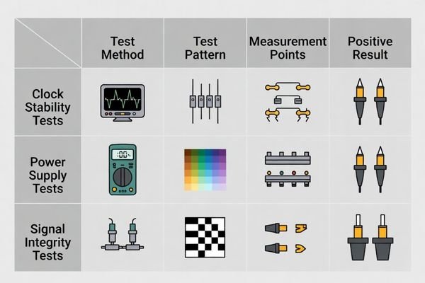
| Potential Cause | How to Isolate and Test | Expected Result if It’s the Cause |
|---|---|---|
| Clock Instability | Keep video mode fixed. Disable SSC or DVFS, lock PLL settings, or switch to a known-stable reference. | Jitter drops significantly or disappears when clock policy is simplified/locked. |
| Power Supply Noise4 | Keep clock policy fixed. Step loads (backlight brightness, CPU stress, motors). | Jitter intensity correlates strongly with load and rail noise. |
| Cable / SI Issues | Keep software and load constant. Test shorter cable, reseat connectors, change routing. | Artifacts change with cable handling; may show sparkles/dropouts or intermittent sync loss. |
A fast field clue is the boot transition: if you can identify the moment jitter begins (bootloader → OS), suspect driver-initiated clock/power policy changes first. Next step: measure at the module connector to turn the symptom into evidence.
What measurements and experiments pinpoint the unstable clock mechanism?
Once clock instability is suspected, objective measurement at the right location is what separates a real fix from trial-and-error.
Probe the pixel clock and relevant rails at the LCD module connector, not only at the SoC, and correlate waveform changes with on-screen jitter. Then run minimal-change experiments—disable SSC, lock PLL settings, disable DVFS, vary temperature and load—and confirm the measured clock instability follows the same changes as the visible jitter.
Turn the problem into a reproducible “good vs jitter” comparison:
Measurement Setup
Probe the pixel clock and key timing signals as close to the module connector as practical. What matters is the clock the module sees, which can differ from upstream nodes due to harness impedance and grounding. Use appropriate probing (short ground techniques and bandwidth suitable for the clock) and also measure the PLL/clock-rail supplies, because rail ripple and reference noise can directly increase phase noise.
Controlled Experiments
Capture waveforms in both phases—stable and jittering—then perform minimal-change tests:
- Disable SSC: If SSC is enabled after OS load, test with SSC off and compare measured clock stability and visible jitter.
- Lock PLL / disable DVFS: Remove dynamic switching. If jitter drops, policy-driven reconfiguration is implicated.
- Thermal and load sweeps: Warm the system, vary CPU load, and step backlight brightness. If rail noise changes in sync with measured clock instability and visible jitter, power integrity is a likely driver of clock phase noise.
- Bridge/scaler checks: If present, confirm whether it re-locks or changes reference after boot and whether that aligns with jitter onset.
The goal is to make the mechanism explicit: “jitter starts when policy X enables,” or “jitter tracks PLL rail ripple5 under load,” so the fix is targeted.
FAQ
Why does the image jitter only after the OS loads, not during the boot logo?
OS stages often enable SSC, DVFS, or different PLL configurations; those policy changes can increase clock phase noise or alter timing behavior.
Can power rail ripple create a clock jitter symptom?
Yes. Noise on PLL supply rails or ground reference can increase phase noise and appear as visible image jitter even when timing parameters are unchanged.
How can I quickly tell if it’s timing shift or clock jitter?
Timing shift is usually a stable offset with fixed black bars; clock jitter looks like continuous shimmer or micro-motion of edges and fine lines.
Where should I probe to see the problem most accurately?
At the module connector for pixel clock and local rails, because what the module sees can differ from regulator nodes due to harness impedance.
When is customization preferable for persistent post-boot jitter?
If the platform clock policy can’t be made deterministic or the power/EMI environment is harsh, tailoring the clock/power integration can reduce field risk.
Conclusion
Post-boot image jitter is best treated as a clock-contract problem: confirm the motion is clock-like, correlate onset to post-boot policy changes, and measure pixel clock behavior at the module connector while manipulating SSC/DVFS/PLL settings, temperature, and load. When jitter aligns with PLL or policy transitions, fixes typically involve locking clock sources, validating SSC behavior, and cleaning PLL supplies and references—then proving stability with regression tests across boot stages.
At LCD Module Pro, we help teams diagnose post-boot jitter by focusing on connector-level measurement, controlled A/B experiments, and integration-aware validation so LCD display modules remain stable from boot through runtime states.
✉️ info@lcdmodulepro.com
🌐 https://lcdmodulepro.com/
-
Exploring DVFS will enhance your knowledge of power management techniques, vital for efficient system performance. ↩
-
Signal integrity problems can severely affect video quality. Discover more about these issues and solutions to ensure optimal performance. ↩
-
Understanding Pixel clock PLL is crucial for optimizing display performance and reducing phase noise. ↩
-
Exploring power supply noise can provide insights into improving device stability and performance. ↩
-
Exploring PLL rail ripple can help identify issues affecting clock stability, leading to better system performance. ↩