Selecting the right LCD display module can make or break your device design. A mismatched display not only compromises user experience but can lead to costly redesigns and field reliability issues.
When choosing an LCD display module, success depends on systematically evaluating three interconnected factors: the physical size and form factor must align with your mechanical and UI needs, the interface must match your platform capabilities, and the lifetime characteristics must suit your operating environment.
In real industrial and automotive-style integrations, display decisions quickly cascade into enclosure design, cable routing, EMI/EMC risk1, power budgeting, and thermal reliability. The safest approach is to start with measurable requirements, then evaluate size, interface, and lifetime together as one system—so you don’t end up with a display that looks perfect on paper but fails mechanical fit, becomes unstable on a long cable, or degrades too fast in the field.
Start with Your Real Requirements: Use Case, Environment, and Constraints
Before diving into display specifications, you need to clearly define how your device will actually be used and what constraints it must work within.
The most successful display integrations start by documenting three critical aspects: the usage pattern (content type, viewing distance, touch requirements), the operating environment (temperature, ambient light, shock/vibration), and the hard constraints (mechanical envelope, power budget, cost target, lifetime requirements).
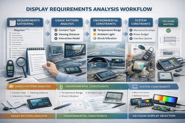
Understanding these fundamental requirements helps prevent costly selection mistakes. A practical way to capture them is to build a short “display input sheet2” before you compare modules: target active area and viewing window, maximum outline thickness, connector orientation and cable exit direction, allowable cable length, host platform display output options, target brightness under real ambient light, operating temperature range, expected hours per day, and what “end-of-life” performance still must be acceptable (brightness maintenance and color shift). With these inputs defined, you can quickly filter out displays that will cause late rework—like a panel that fits the window but forces an impossible bend radius, or a bright option that your thermal design cannot support for the required duty cycle.
Usage Pattern Analysis
Your content and interaction model drives many technical choices. Text-heavy applications need higher resolution for readability, while simple status displays can use lower resolution to reduce interface complexity. Touch interfaces require careful consideration of optical bonding and cover glass options. If users view the screen from farther away, readability typically benefits from appropriate pixel density and stable contrast; if the device is used at close range with simple icons, you can often reduce resolution and simplify bandwidth without compromising usability. If touch is required, treat the touch/cover stack as part of the display system because it can change reflections, perceived brightness, and the mechanical stack-up.
Environmental Constraints Mapping
The operating environment sets critical boundaries for your selection. Indoor kiosks face different challenges than vehicle displays or outdoor equipment. Temperature range, ambient light, and mechanical stress must be factored into specifications for brightness, thermal design, and mechanical mounting. If the device will face strong ambient light or direct sun, you may need a higher-brightness direction and better reflection control; if the device lives in vibration/shock conditions, connector retention, mounting strategy, and harness strain relief become reliability drivers; if humidity and temperature swing are real, condensation prevention and sealing choices should be planned early and validated with testing.
Choosing the Right Size: Diagonal, Aspect Ratio, Resolution, and Mechanics
The physical characteristics of your display module must harmonize with both your user interface design and your mechanical constraints.
Display size selection requires balancing multiple factors: the diagonal measurement affects overall device proportions, the aspect ratio determines content layout options, the resolution impacts interface bandwidth and processing requirements, and the mechanical specifications influence mounting and integration complexity.
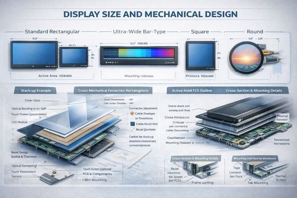
Modern display applications demand creative form factors. Ultra-wide displays3 offer efficient status visualization, while square or round displays enable distinctive product aesthetics. However, these choices bring specific integration challenges. Treat “size” as a combination of active area, outline, and thickness, not just diagonal. Also remember that higher resolution increases pixel bandwidth and processing load, and may raise power and heat—so it should be selected to meet readability needs rather than as a default upgrade.
Form Factor Optimization
Consider how different aspect ratios affect your product’s visual identity and usability. Ultra-wide modules like BU215X excel in dashboard applications, while square formats like SQ220S create unique user experiences in premium devices. A useful rule of thumb is: if your UI is mostly status, alarms, and key metrics arranged in a strip, an ultra-wide bar format can be the most space-efficient; if your UI needs a central “hub” layout, square can be easier to design and more visually balanced; if your product experience is dial- or gauge-like, round can align naturally with the interaction model.
Mechanical Integration Planning
Success requires detailed attention to mounting methods, cable routing, and thermal management. Verify active area placement, outline dimensions, and connector locations early in the design process. Consider the complete stack-up including touch sensors, optical bonding, and protective covers. If you add touch/cover glass, assume you must re-check brightness and reflections (optical losses and glare), and re-check thickness and tolerances (bezel fit, gasket compression, and assembly process). Planning these items early prevents late conflicts such as connector interference, insufficient keep-out zones, or a front stack that looks good but reduces perceived clarity.
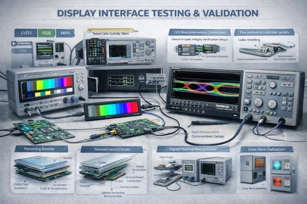
Picking the Interface: Bandwidth, Cable Length, EMC, and Platform Compatibility
The interface between your host system and display module is critical for reliable operation.
Select your display interface based on your system’s capabilities and real-world constraints. Consider not just the raw bandwidth requirements, but also EMC performance, cable routing limitations, and long-term compatibility with your chosen platform.
- Maximum cable length for your chosen interface
- EMI/EMC requirements in your application
- Platform-specific timing constraints
- Connector and cable availability
Interface selection requires careful validation under real conditions. A solution that works in development may face challenges in production without proper attention to signal integrity and EMC design. A practical selection flow is: confirm what your SoC/MCU can output, estimate the bandwidth needed by your resolution and refresh, then evaluate whether your cable length and enclosure grounding give enough margin. If your cable run is longer, your environment is noisier, or EMC requirements are strict, plan for stronger verification, shielding, and layout rules early—because “bench stable” does not guarantee “production stable.” When direct compatibility is difficult, a controller/bridge approach may simplify integration and debugging, but it adds cost, power, and thermal considerations that should be included in the system trade-off.
Designing for Lifetime: Backlight Aging, Thermal Margin, and Reliability Risks
A display module’s service life depends heavily on how you manage its operating conditions.
Long-term reliability requires building adequate margins into your thermal design, carefully managing backlight intensity, and protecting against environmental stresses. The same display module can have dramatically different lifetimes depending on how these factors are managed.
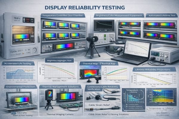
Engineering successful long-term reliability requires attention to multiple factors. In many applications, “lifetime” is dominated by the LED backlight and how it is driven: higher brightness and higher temperature accelerate aging, and continuous full-power operation can shorten useful life. Define lifetime targets in terms that match your product reality—expected operating hours per day, acceptable brightness at end-of-life, and acceptable color shift—then design your brightness control strategy and thermal margin to support those targets.
Thermal Management Strategy
Proper heat dissipation is crucial for LED backlight longevity. Design adequate thermal paths and verify temperature rise under worst-case conditions. If high brightness is required, avoid treating maximum brightness as a permanent operating point; implement dimming curves, ambient-light compensation, and sensible limits so the backlight is not continuously operated at maximum stress. This combination—thermal path plus drive strategy—is often the difference between stable long-term performance and early field degradation.
Environmental Protection Design
Implement appropriate sealing, condensation prevention, and mechanical isolation based on your operating environment. Validate designs through accelerated life testing5 that reflects real usage patterns. If your device faces humidity and temperature swings, condensation risk should be addressed at the mechanical design stage (not after failures occur). If the product is subject to vibration/shock, prioritize stable mounting, connector retention, and strain relief to reduce intermittent failures that can be misdiagnosed as “panel issues.”
Recommended MEIDAYINGNUO LCD Display Module Models for Common Scenarios
From supporting diverse industrial and commercial applications, I’ve identified how different display requirements map to optimal module selections.
MEIDAYINGNUO offers field-proven display solutions with comprehensive engineering support, detailed documentation, and reliable supply chains. Our module selection process considers not just basic specifications, but also long-term serviceability and integration requirements.
| Role / Application | Usage Pattern | Display Requirements | Recommended Model | Key Integration Considerations |
|---|---|---|---|---|
| Status Displays | 24/7 Information Display | High Reliability, Wide Viewing Angle | BU156X | Thermal Management, Cable Routing |
| Industrial HMI | Interactive Control | Touch Compatible, Indoor Readability | SQ220S | EMC Design, Mounting Method |
| Outdoor Kiosks | Sunlight Viewable | High Brightness, Environmental Protection | HB215X | Thermal Solution, Power Budget |
| Vehicle Displays | Information Dashboard | Wide Temperature, Vibration Resistant | BU215X | Mechanical Stability, EMI Shield |
| Premium Devices | Distinctive UI | Unique Form Factor, Premium Look | RD157H | Optical Bonding, Cover Glass |
Treat these recommendations as a shortlist, not an assumption of drop-in compatibility. Final selection should be confirmed against your platform interface, cable length, mechanical envelope, optical stack (touch/cover), and end-of-life brightness target. If your constraints are tight—such as long cables, strict EMC, high ambient temperatures, or 24/7 high-brightness operation—early system-level verification is the fastest way to avoid late redesigns.
FAQ
What’s the most important first step in display module selection?
Start with documenting real usage requirements and constraints – viewing conditions, environment, power limits, and mechanical boundaries. This prevents selecting a display that looks good on paper but fails in practice.
How do I balance brightness and lifetime requirements?
Higher brightness typically reduces lifetime due to accelerated LED aging. Design your thermal solution and brightness control strategy together to maintain acceptable brightness over the required service life.
When should I consider custom display solutions?
Consider custom options when standard modules don’t meet critical requirements in size, interface, or reliability. However, evaluate the impact on development time, cost, and long-term supply stability.
What are common EMC/EMI challenges with display interfaces?
High-speed interfaces can create EMI issues, especially with longer cables or in noisy environments. Proper shielding, cable routing, and interface selection based on actual conditions are essential.
How do environmental factors affect display selection?
Temperature, humidity, shock/vibration, and ambient light all impact display performance and lifetime. Match specifications to your worst-case conditions and validate with appropriate environmental testing.
Conclusion
Successful LCD display module selection requires a systematic approach that considers size, interface, and lifetime requirements as an interconnected system. By carefully evaluating real-world usage requirements, environmental conditions, and integration constraints, you can choose a display solution that delivers reliable performance throughout your product’s service life.
MEIDAYINGNUO specializes in providing engineered display solutions that meet demanding industrial and commercial requirements. Our team can help you navigate these technical decisions and validate your design choices. For detailed discussion of your specific application requirements, please contact our engineering team.
✉️ 961531917@qq.com
🌐 https://lcdmodulepro.com
-
Understanding EMI/EMC risk is crucial for ensuring reliable performance in industrial applications. Explore this link for expert insights. ↩
-
Exploring this resource will provide insights into creating effective input sheets for better module selection. ↩
-
Explore how Ultra-wide displays enhance visualization and user experience in various applications. ↩
-
Understanding Signal Integrity Analysis is crucial for ensuring reliable performance in electronic designs, especially in production. ↩
-
Exploring accelerated life testing can provide insights into validating designs under real-world conditions, enhancing product reliability. ↩