For many applications, from automotive dashboards to kiosks and industrial controls, the ability of an LCD display module to dim to a very low, stable brightness is a critical feature. A “night mode” must be comfortable for human eyes in dark environments and free of distracting artifacts. However, achieving stability at the bottom end of the dimming range is often a system-level engineering challenge because the backlight control loop, power delivery, thermal behavior, and even human perception become more sensitive at low luminance.
To validate stable low-brightness dimming, you must test for the absence of visible flicker, pulsing, and banding, while ensuring luminance is repeatable and drift-free at the lowest usable settings. This requires a validation setup that combines controlled visual inspection with objective luminance-versus-time measurement, while logging electrical and thermal conditions so results remain repeatable across labs and builds.
In LCD display module integration work at LCD Module Pro, low-brightness performance is a frequent source of late-stage surprises. A display that looks excellent at 100% brightness can show flicker, pulsing, or unevenness at 1% brightness. The common mistake is to assume dimming is a simple, linear scaling problem. In reality, the behavior of the backlight driver1, the power supply, and the viewer’s sensitivity all become non-linear and less forgiving at very low light levels.
Proper validation is not just confirming that the display “gets dim.” It is proving that it gets dim in a smooth, controlled, and repeatable way without introducing new artifacts. This requires treating the display module, the backlight driver, and the host system as one interconnected control loop. The goal is to ensure the user experience remains stable in a dark room, not only in broad daylight.
What does “stable low-brightness dimming” really mean in LCD module validation?
The term “stable” has a specific, multi-faceted meaning in the context of dimming validation. It goes beyond reaching a low luminance value and focuses on whether low-level output is visually comfortable and measurably repeatable under realistic conditions.
“Stable low-brightness dimming” means the display can maintain a commanded low luminance level without visible flicker, shimmer, or pulsing, while remaining uniform across the screen, smooth when changing levels, and repeatable across operating conditions such as temperature and supply voltage.
When defining a validation plan, it helps to break “stability” into practical attributes that can be tested and documented:
- Temporal stability2: Brightness should not fluctuate or “breathe” over time. This means no visible flicker to the eye and no periodic modulation that an imaging system might capture.
- Spatial uniformity: Dimming should remain even across the entire screen. Some designs reveal blotches, bands, or uneven patches only at very low brightness.
- Smoothness at the bottom end: Stepping brightness one code at a time near the minimum should not create sudden jumps. This depends on effective control resolution and a well-behaved backlight control loop.
- Repeatability: The same dimming command should produce the same luminance after warm-up, across expected ambient temperatures, and under minor supply variation.
A display that satisfies these points delivers a low-brightness experience that feels stable to users and behaves predictably in validation data.
Which backlight control methods affect low-level stability, and how can issues appear?
Most low-brightness instability originates in the backlight unit (BLU) and its driver, not in the LCD pixels themselves. The method used to dim the LEDs largely determines which artifacts can appear at the bottom of the dimming range.
Pulse-width modulation (PWM) and analog (current) dimming are the two main control methods, and both can create low-level issues. PWM can introduce visible flicker or camera banding, while analog dimming can suffer from non-linearity, color shift, or driver instability as current approaches the minimum regulation threshold.
From an engineering standpoint, it is useful to evaluate the backlight driver strategy as a control loop and verify it with objective evidence.
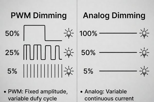
PWM Dimming
This method rapidly turns the LEDs on and off, and perceived brightness is determined by duty cycle (on-time vs. off-time).
- How it fails: If PWM frequency is too low, some users may perceive flicker, especially in peripheral vision. At very low duty cycles, limited duty resolution can create visible “steps” or jumps between adjacent brightness codes. PWM can also create camera banding or beating artifacts depending on shutter speed and frame rate.
- How to validate: Use a photodiode to capture luminance-versus-time at the lowest settings and analyze periodic components tied to PWM. If cameras matter, record video while sweeping shutter speed/frame rate to reveal banding sensitivity.
Analog Dimming3
This method controls brightness by adjusting constant current through the LEDs.
- How it fails: Drivers can become non-linear or unstable near minimum current, creating pulsing, drift, or unpredictable output changes that vary with temperature and load. Low-current operation can also change LED spectral behavior, causing a visible color shift.
- How to validate: Measure luminance over time during warm-up and temperature sweeps while logging driver input voltage and (if available) LED current to correlate drift or pulsing with regulation limits.
Many modern systems use hybrid dimming, combining analog dimming at higher levels with PWM at lower levels. This can be effective, but the crossover point can introduce a visible discontinuity if not tuned. Validation should include small-step transitions around the crossover at warm and cold conditions to confirm continuity.
How do you design a validation setup that matches human vision and camera requirements?
A strong validation setup must detect issues visible to human observers and also artifacts that only appear in captured images. This usually requires separating subjective checks from objective measurement, while keeping both representative of real use.
Design a validation setup with controlled ambient lighting for visual checks and use a calibrated light meter or fast photodiode to objectively measure luminance over time. For camera-specific validation, test representative camera settings across shutter speeds and frame rates to detect PWM-induced banding and beating at low brightness.
Based on typical integration projects, a robust setup includes:
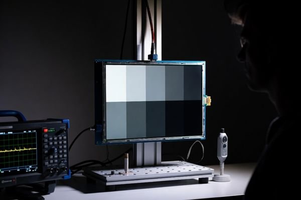
- Controlled environment: Test in a dark room or controlled enclosure to minimize stray light and keep comparisons consistent.
- Human visual inspection: Use trained observers to look for flicker, shimmer, pulsing, and low-level non-uniformity. Dark or mid-gray patterns are more revealing than full white for low-brightness instability.
- Objective measurement4: Use a fast photodiode or a high-quality light meter connected to a data logger to record luminance versus time. Log supply voltage at the driver input and module temperature simultaneously to correlate any instability with electrical or thermal events.
- Camera testing (when applicable): Record video using a representative camera while sweeping shutter speeds and dimming levels to look for rolling bands or beating. Keep the test pattern and exposure settings fixed and documented so results are repeatable.
What acceptance criteria can you use to judge low-brightness dimming as “stable”?
Vague criteria like “no flicker” are not useful. Good acceptance criteria are measurable, repeatable, and clearly tied to the intended use case.
Stable dimming acceptance criteria should combine visual thresholds (for a defined pattern, distance, and ambient condition) with measurable limits on luminance ripple and drift at the lowest usable settings, and include camera artifact checks when imaging is part of the application.
Here is a table of sample acceptance criteria that can be adapted for a validation plan:
| Category | Criterion | Measurement Method |
|---|---|---|
| Visual Stability5 | No visible flicker or pulsing on dark/gray patterns under defined viewing conditions. | Human observation in a controlled environment. |
| Smoothness | No visible jump when changing brightness by a single step at the bottom 10% of the range. | Human observation while stepping through dimming codes. |
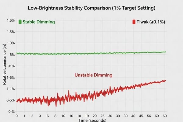
| Temporal Stability | Luminance ripple (max-min)/avg stays below a defined limit over a defined time window at the lowest usable setting. | Photodiode + Oscilloscope/Data Logger. |
| Drift | Luminance stays within a defined drift band from a defined time after power-on to the end of the warm-up interval. | Light meter + Data Logger. |
| Camera Artifacts | No visible rolling bands at representative shutter speeds and frame rates for the application. | Camera recording + Visual inspection of video. |
These criteria turn a subjective concept into a clear pass/fail test, while still allowing you to tune numeric thresholds to match product requirements and measurement methods.
How do you choose an LCD display module for reliable low-brightness dimming performance?
Selecting the right module early is one of the most effective ways to reduce low-brightness risk. This requires looking beyond front-page brightness numbers and focusing on how the backlight is controlled at the bottom end.
To choose a module for reliable dimming, define your minimum brightness target and whether camera compatibility is needed, then evaluate the backlight control strategy for stable regulation at low output. Prioritize modules with clear documentation on dimming behavior and suppliers that can support low-level validation with consistent, controlled revisions over product life.
Here is the selection strategy to de-risk integration:
- Define your use case: Specify the lowest usable brightness, the ambient conditions, and whether a camera will capture the display.
- Scrutinize the backlight system: Ask about dimming method (PWM, analog, hybrid), effective control resolution, and any known low-level limits such as minimum regulation behavior. A good supplier should be able to discuss these constraints clearly.
- Evaluate power and thermal design: Stable dimming depends on clean power and predictable thermal behavior. Consider mounting, heat dissipation, and whether temperature gradients could cause drift.
- Prioritize documentation and support: Choose a supplier that provides detailed technical information and responsive technical support for validation.
- Manage lifecycle risk: Select a module with stable supply continuity and strong change control so validated dimming performance does not change unexpectedly in future production batches.
FAQ
Why does flicker become more noticeable at very low brightness?
At low luminance, human vision becomes more sensitive to temporal modulation, and any ripple from PWM or driver regulation can stand out. Additionally, low-level control may have fewer effective steps, making small variations more visible as discrete changes.
How can I tell if the issue is PWM frequency versus driver instability?
PWM-related artifacts tend to correlate with specific shutter/frame settings and show periodic components tied to the PWM rate, while driver instability may appear as irregular pulsing or drift that changes with temperature and load. Measuring luminance over time with a photodiode can distinguish periodic from irregular behavior.
Why does dimming look fine on white but unstable on gray or dark patterns?
Low-level nonuniformity, temporal dithering interactions, and small ripple components are easier to see on mid-gray or dark content. Full white can mask banding and subtle modulation, so pattern selection is part of proper validation.
What should I log during validation to make results repeatable?
Log the dimming command value, supply voltage at the driver input, backlight current (if available), module temperature, ambient temperature, and measured luminance versus time. Pair logs with the exact test pattern and camera exposure settings when relevant.
Can low-brightness instability be caused by power distribution rather than the module itself?
Yes. Supply ripple, ground bounce, or insufficient decoupling can modulate the driver or control signals, producing flicker or pulsing that looks like a module issue. Validating at electrical corners helps separate module behavior from system power problems.
How do I avoid a visible “jump” at the hybrid dimming crossover point?
Ensure the PWM duty and analog current curves are matched in the crossover region, and validate with small-step transitions around the crossover under warm and cold conditions. A well-tuned crossover should look continuous to both the eye and the photometric measurement.
Conclusion
Validating stable low-brightness dimming is a critical part of developing products used in varied lighting conditions. Success requires moving beyond a simple check of minimum brightness and adopting a system-level validation approach. Common failures—flicker, pulsing, banding, drift, and low-level non-uniformity—are typically rooted in the backlight control strategy and its interaction with the system’s power and thermal environment. By combining controlled visual checks with objective luminance-versus-time measurement and clear acceptance criteria, you can build a repeatable validation process that holds across operating conditions.
At LCD Module Pro, we focus on supporting customers through these integration challenges with clear technical information and responsive engineering support. By partnering with a knowledgeable supplier and implementing a rigorous validation plan, you can ensure your product’s “night mode” delivers a comfortable and consistent low-brightness experience.
✉️ info@lcdmodulepro.com
🌐 https://lcdmodulepro.com/
-
Exploring the role of backlight drivers can enhance your knowledge of display technology and improve product design. ↩
-
Understanding temporal stability is crucial for ensuring consistent brightness in displays, enhancing user experience. ↩
-
This resource will provide insights into Analog Dimming’s impact on LED behavior, essential for effective design. ↩
-
Exploring objective measurement techniques can improve your testing methods and ensure consistent results. ↩
-
Explore this link to understand how visual stability impacts user experience and product quality. ↩