Selecting LCD display modules for harsh environments requires systematic protection architecture design, focusing on ingress prevention, vibration mitigation, and long-term reliability under combined environmental stresses.In harsh environments, LCD display module selection depends on creating a complete protection system rather than relying on module features alone. Success requires coordinated front barrier design, controlled sealing strategies, vibration-resistant mounting, and thermal management to prevent condensation and corrosion over extended operating cycles.
In my LCD display module integration work at MEIDAYINGNUO, I’ve learned that environmental failures1 rarely result from single exposure events. Instead, they develop through combined stress mechanisms: dust infiltration that degrades optical clarity, moisture ingress that enables corrosion, and vibration that accelerates connector wear and mechanical fatigue. A robust approach addresses these failure modes systematically through protection architecture rather than assuming any component is “rugged enough” on its own.
What makes an environment "harsh" for an LCD display module?
Harsh environments attack multiple vulnerability points simultaneously, creating cascading failure mechanisms.
Environmental harshness is defined by dust infiltration that causes optical contamination, moisture that creates condensation and corrosion paths, and vibration that accelerates connector fretting, fastener loosening, and FPC fatigue. The severity depends on exposure duty cycles, temperature swings, and chemical contact risks.
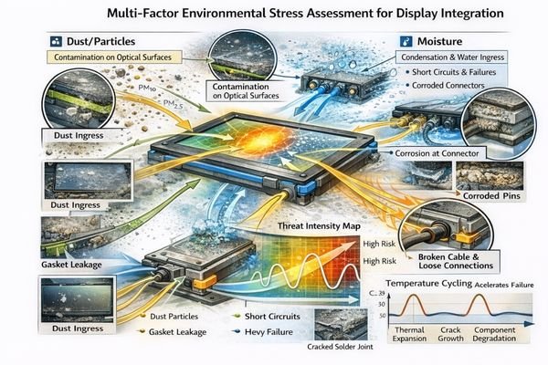
From an engineering standpoint, I usually evaluate harshness by how quickly the environment can compromise the module’s optical stack, mechanical retention, or electrical continuity. Temperature cycling amplifies these effects by causing material expansion, condensation events, and seal degradation. The key insight is that "mostly sealed" designs become failure-prone when multiple stresses combine with thermal cycling, so I plan for combined exposure rather than isolated test conditions.
Dust and Contamination Mechanisms
Dust particles infiltrate through microscopic gaps and accumulate on optical surfaces, reducing contrast and creating visible artifacts. To make this actionable, I start by mapping likely ingress paths: front-panel joints, enclosure seams, button/knob interfaces, and any cable entry points that can “breathe” under pressure changes or vibration. Then I define what “contamination failure” means for the product—such as an acceptable limit for visible spots, haze, or edge-light leakage—because without a pass/fail criterion, dust issues become subjective and recur in the field. The most common mistake I see is focusing only on the front window while leaving a hidden path that deposits dust onto the viewing area over time, especially when vibration causes micro-pumping. If the product includes touch, I also check how static charge and surface conditions can attract fine particles and concentrate contamination in specific zones.
Moisture and Corrosion Pathways
Moisture enables galvanic corrosion at connector interfaces, creates conductive bridges between circuits, and degrades adhesive bonds. Condensation during temperature transitions can introduce moisture even in nominally sealed systems, making thermal management2 critical for reliability. In practice, I evaluate when and where moisture will appear by looking at dew-point crossings, cold-start behavior, and any exposure to spray, fog, or washdown procedures, then identifying the “first wet location” inside the enclosure. A typical failure pattern is corrosion or rising contact resistance at the connector/FPC region, so I treat that area as a primary risk zone and define measurable criteria such as electrical stability under vibration and temperature cycling, and whether any residue or corrosion products appear after representative exposure. A common integration error is assuming that a tight seal alone prevents condensation; in reality, trapped humidity plus temperature gradients can still create moisture on cold surfaces.
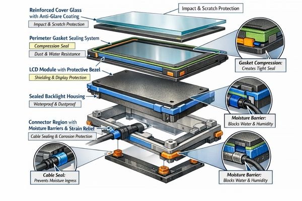
How should you design sealing and front protection for dust and moisture?
Effective protection requires a coordinated barrier system rather than relying on individual component sealing.
I treat the front-of-panel as a controlled barrier system combining cover lens protection, perimeter gasket or adhesive bond lines, and enclosure interface design. The sealing strategy must accommodate assembly tolerances, service requirements, and pressure changes while preventing ingress and managing trapped moisture.
When I troubleshoot field issues on products integrating LCD display modules, I often find that sealing failures3 start with incompatible assembly tolerances or inadequate pressure relief. Overly aggressive adhesives reduce serviceability while weak gaskets can pump contaminants under vibration. Moisture protection extends beyond keeping water out—it requires managing temperature gradients and providing controlled moisture escape paths when necessary. I also treat sealing as a system trade-off: stronger sealing can increase trapped-humidity risk and make rework harder, while more serviceable interfaces may require better control of compression, surface finish, and assembly processes to remain reliable under vibration and pressure changes.
What mounting and interconnect choices reduce vibration failures?
Vibration failures typically begin as micro-motion that creates intermittent electrical faults before developing into hard failures.
Robust vibration resistance requires stable mounting datums, evenly distributed retention points, and stress concentration avoidance near backlight edges and connector zones. Interconnect protection emphasizes strain relief and controlled bend geometry to prevent FPC spring action and connector fretting.
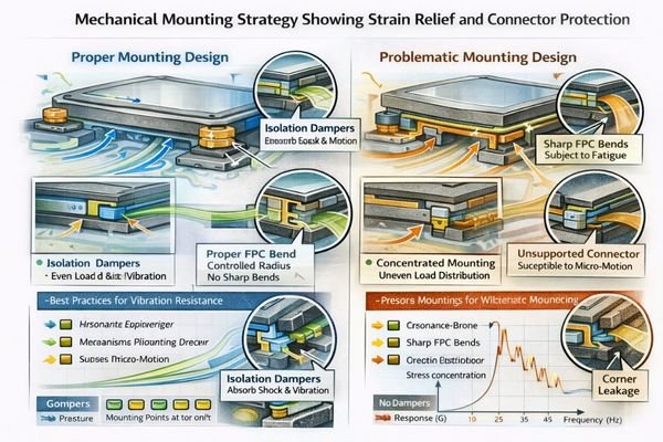
Based on the projects I support with industrial equipment manufacturers, vibration failures4 often manifest as intermittent flicker or touch instability before complete failure. The root cause is usually inadequate strain relief allowing FPC flexing, insufficient connector retention enabling micro-motion, or mounting configurations that create resonance amplification. Practical validation confirms that fasteners remain tight, cable routing prevents pinching, and the module doesn’t act as a vibrating cantilever. To keep decisions consistent, I tie mounting and routing choices back to the vibration source profile (steady motor vibration vs. vehicle resonance vs. impact/shock), because each one demands a different balance of stiffness, damping, and isolation.
| Vibration Source | Failure Mechanism | Protection Strategy |
|---|---|---|
| Equipment Motors | Connector fretting, FPC fatigue | Strain relief, isolation mounting |
| Vehicle/Mobile | Resonance amplification | Controlled stiffness, damping |
| Impact/Shock | Mounting stress concentration | Distributed retention, flex isolation |
Systematic vibration protection addresses both steady-state and transient stress conditions. I use this mapping to decide where isolation is beneficial, where stiffness must be increased, and which locations require strain relief and controlled routing to prevent micro-motion at the connector and FPC transition.
How do you manage condensation, corrosion, and long-term reliability?
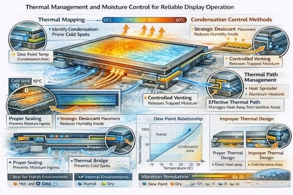
Condensation represents a critical failure mode in temperature-cycling environments, requiring thermal and moisture management strategies.
Condensation prevention requires understanding the complete thermal profile including cold starts, warm-up cycles, internal heat sources, and external exposure patterns. Protection strategies include improved sealing interfaces, corrosion-resistant materials, and controlled moisture management to prevent accumulation at connector and FPC regions.
I evaluate real operating conditions rather than specifications alone: actual temperature gradients, humidity exposure, washdown procedures, and thermal cycling frequency. Reliability depends on how components age under combined stress: backlight degradation, seal compression set, adhesive creep, and contact resistance changes. This requires acceptance criteria based on optical clarity, electrical stability, and mechanical integrity after representative stress exposure. For comprehensive reliability validation support and environmental testing guidance, engineering teams can contact info@lcdmodulepro.com during development planning.
Thermal Management Considerations
Internal heat sources and external temperature variation create condensation-prone conditions. Effective thermal design5 prevents cold surfaces from collecting moisture while maintaining acceptable operating temperatures for electronic components. In practice, I look for cold spots near the front window and around metal brackets, then check whether warm internal air can reach those surfaces and condense during cool-down or cold-start transitions. I also verify that the design has a predictable heat path so temperature gradients are controlled rather than accidental, and I define what “acceptable behavior” is: no visible fogging in the viewing area, no moisture accumulation near connectors, and stable display operation during and after temperature transitions. The common mistake here is validating only at steady-state temperatures; condensation issues often appear during transitions and recovery, not during stable plateaus.
Material Selection and Aging
Corrosion-resistant connector materials, stable gasket compounds, and UV-resistant optical components ensure long-term performance. Material compatibility prevents galvanic corrosion and chemical incompatibility issues that develop over extended operation. To keep this grounded, I treat materials as part of a lifecycle plan: I check how gasket compression changes over time (compression set), whether adhesives creep under temperature and humidity, and how surface treatments hold up under cleaning agents and dust abrasion. For pass/fail thinking, I focus on outcomes that correlate with field failures: whether sealing performance degrades after cycling, whether contact resistance drift causes intermittent behavior under vibration, and whether optical performance remains acceptable after aging and exposure. A frequent oversight is choosing materials that are individually “good” but incompatible together, creating unexpected corrosion couples or bond degradation under humidity and temperature cycling.
How to choose the right LCD display module solution for dusty, wet, vibrating conditions?
Module selection follows a systematic protection architecture approach prioritizing barrier design, sealing integrity, and mechanical survivability.
I select modules by first defining the protection architecture: front barrier strategy, sealing method compatibility, and enclosure interface design to block ingress paths under tolerance and vibration conditions. Then I match optical, electrical, and mechanical requirements to ensure stable performance over the complete operating lifecycle.
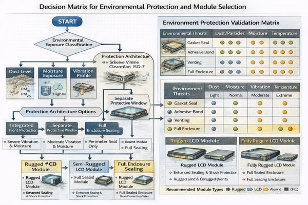
In my experience with harsh environment applications, protection system design matters more than individual component ratings. The module must support the chosen sealing strategy, mounting approach, and interconnect protection while maintaining performance under realistic stress combinations. To make selection and integration predictable, I align on concrete engineering outputs early: a front-of-panel cross-section showing the barrier stack, a sealing-line definition with tolerance and compression windows, connector and cable keep-out zones with strain relief intent, and a validation plan that reflects combined stresses (dust + moisture + vibration + temperature transitions). Custom solutions often provide better protection optimization than attempting to force standard modules into inadequate protection schemes, especially when the enclosure geometry and service requirements leave little margin for trial-and-error.
| Application / Scenario | Usage Pattern | Display Requirements | Recommended Model | Key Integration Considerations |
|---|---|---|---|---|
| Industrial Control | Continuous operation, washdown | High brightness, touch integration | HB215X | Front seal design, connector protection |
| Outdoor Displays | Weather exposure, temperature cycling | Maximum brightness, condensation control | HB238X | Thermal management, moisture barriers |
| Mobile Equipment | Vibration, dust, impact | Rugged mounting, stable interconnect | HB270S | Shock isolation, strain relief |
| Process Monitoring | Chemical exposure, high humidity | Corrosion resistance, sealed interface | SQ332S | Material compatibility, gasket design |
| Custom Environments | Specific protection requirements | Tailored barrier system | Custom | Optimized sealing, mounting, protection |
FAQ
Should I rely on the LCD module itself for dust and moisture protection?
I usually don’t. In harsh environments, protection works best as a system at the front-of-panel: cover lens or window, gasket or bond line, and enclosure interface. The LCD display module selection then supports this architecture with compatible mounting and interconnect design.
How do I reduce condensation risk without over-sealing the enclosure?
I assess the temperature cycle and internal heat sources first. Then I balance sealing with moisture management—using controlled venting strategies or design measures that avoid trapping humid air near cold surfaces, while keeping ingress paths blocked.
Why does my display flicker under vibration?
Intermittent flicker, momentary blanking, or touch instability often appears before a hard failure, and it frequently traces back to micro-motion at connectors, insufficient strain relief, or rubbing/pinching in the cable path.
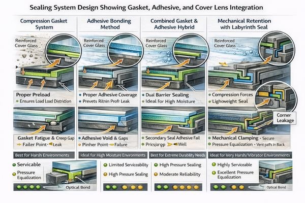
Do gaskets always work better than adhesive bonding for harsh environments?
Not always. I choose based on tolerance control, serviceability, and vibration profile. Gaskets can enable rework but may "pump" dust if compression is inconsistent; bonding can seal well but reduces service access and needs tight process control.
How should I protect the interface and cable path against dust and moisture?
I keep ingress paths away from connectors, add strain relief, and ensure the cable route doesn’t create capillary paths for moisture. I also plan ESD protection near front-panel entry points so environmental exposure doesn’t become an electrical weakness.
What validation is most meaningful for dust, moisture, and vibration together?
I prefer combined-stress thinking: verify sealing integrity, electrical stability, and optical cleanliness after realistic assembly tolerances, vibration exposure, and temperature cycling that can trigger condensation—not just isolated single-factor checks.
Conclusion
In dusty, moist, and vibrating environments, the optimal LCD display module fits within a complete protection and reliability architecture that addresses ingress prevention, condensation control, and vibration mitigation simultaneously. Success requires systematic design of front barriers, sealing strategies, and mounting approaches rather than relying on individual component specifications. As an engineer, I prioritize reducing field failures by validating protection systems under combined environmental stresses that match real operating conditions, using a repeatable principle: barrier design, sealing integrity, and vibration-proof interconnect decisions must work together as one system.
MEIDAYINGNUO provides environmental protection expertise for LCD display module integration including high-brightness modules for outdoor applications, ruggedized mounting solutions, and custom protection architectures for challenging environments. Our engineering team supports sealing design, vibration analysis, and reliability validation to ensure stable performance under dust, moisture, and mechanical stress conditions. Contact our team when developing displays for demanding environmental requirements.
✉️ info@lcdmodulepro.com
🌐 https://lcdmodulepro.com/
-
Understanding environmental failures can help you design better protection strategies for LCD displays. ↩
-
Learning about thermal management can enhance your knowledge of maintaining product performance in varying conditions. ↩
-
Understanding sealing failures can help you improve product reliability and prevent future issues. ↩
-
Understanding vibration failures can help you implement effective strategies to prevent equipment malfunction. ↩
-
Understanding effective thermal design is crucial for preventing condensation and ensuring reliable electronic performance. ↩