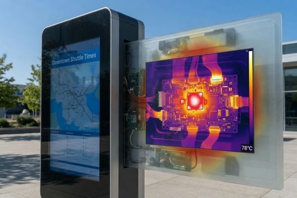
A high brightness LCD module can look very convincing during the first power-on test. The UI is clear, the screen looks bright, and the nit value appears to match the project target. The real question usually comes later: what happens after the module is installed into the actual enclosure and runs for several hours?
That is where thermal management becomes important. A brighter backlight brings more electrical load, and part of that power becomes heat. If the heat has no reliable path to leave the LCD module area, the display may still pass a short sample test but become less stable in real operation.
Thermal management for high brightness LCD modules is about checking whether the backlight, driver, enclosure, ambient temperature, duty cycle, and heat path can support stable brightness over time. The concern is not only peak luminance, but whether the module can keep usable brightness inside the final device.
A high brightness LCD module is not simply a standard module with a stronger backlight. It often needs more backlight power, stronger LED driving, and a better heat path1. If the enclosure is sealed, the driver board sits in a hot area, or the metal frame has poor thermal contact with the device structure, heat can stay near the display instead of spreading away.
This matters most in outdoor kiosks, transportation systems, marine equipment, vehicle-mounted terminals, and sealed industrial devices. These projects often combine long operating hours, direct sunlight, high ambient temperature, and limited airflow. Once the enclosure depth, bracket, sealing method, and driver position are fixed, thermal changes become much harder and more expensive.
Why High Brightness LCD Modules Need Thermal Management
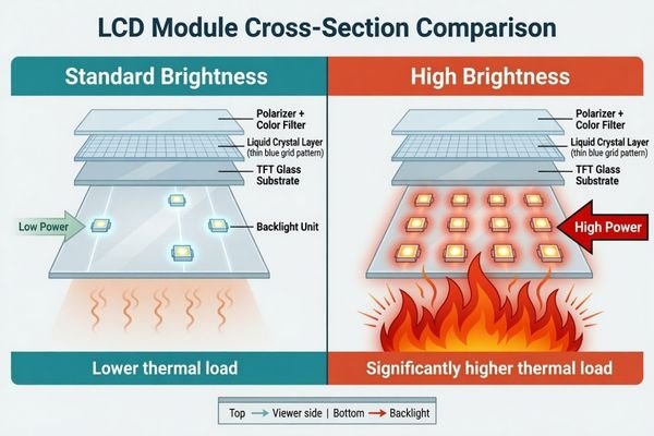
A high brightness LCD module usually reaches higher luminance through a stronger backlight system. That normally means higher LED current, higher backlight power, and more heat around the display area. Not all electrical energy becomes visible light. Some of it becomes thermal load that the product structure has to handle.
Higher brightness targets should be reviewed together with backlight power, driver placement, enclosure space, duty cycle, thermal path, and expected ambient temperature. A high nit value is useful only when the final device can support it safely.
In a high brightness LCD module review, the first items I would check are the brightness target, backlight power, driver board location, available enclosure space, expected ambient temperature, and daily operating mode. These details say more about real integration risk than the nit value alone.
A high brightness module should not be treated as a direct drop-in replacement for a standard module. The same enclosure that works for a normal-brightness display may not have enough thermal margin for a stronger backlight. If there is no airflow, weak frame contact, limited chassis conduction, or a hot internal layout, the higher-brightness option may create a new problem instead of solving visibility.
You can Explore high brightness display modules when comparing brightness targets, backlight power, optical structure, and thermal feasibility for outdoor or high-ambient-light applications.
How Heat Affects Brightness Stability
Peak brightness during a short test is not the same as stable brightness in the field. Datasheet brightness is normally measured under controlled conditions. In the final product, the LCD module may run inside a sealed enclosure, under sunlight, or in a high-temperature environment for many hours.
Heat can affect brightness stability because LED efficiency, driver behavior, and system protection strategy may change as temperature rises. A module may reach the target luminance at startup, then become dimmer after heat builds up inside the enclosure.
For brightness stability, I would not stop at a short bench test. I would want to see whether the module can maintain usable luminance after running inside the real device structure, with the expected brightness setting and operating mode.
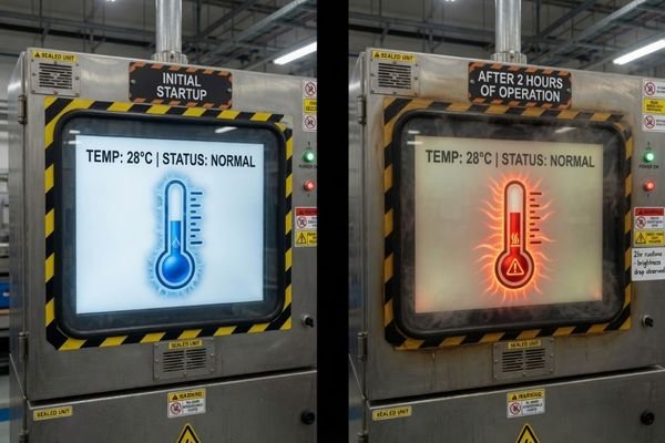
This issue often appears only after the device has been running for a while. The module may look bright during sample approval, but once the temperature rises, the backlight driver or customer system may reduce output depending on the protection strategy2. From the user’s side, the result is simple: the display becomes harder to read, even though the selected module was specified as high brightness.
For sunlight readable LCD applications, this matters more than many teams expect. A screen that starts bright but gradually loses luminance after heat buildup may not provide reliable outdoor visibility during a full working day.
How Thermal Stress Impacts Backlight Lifetime
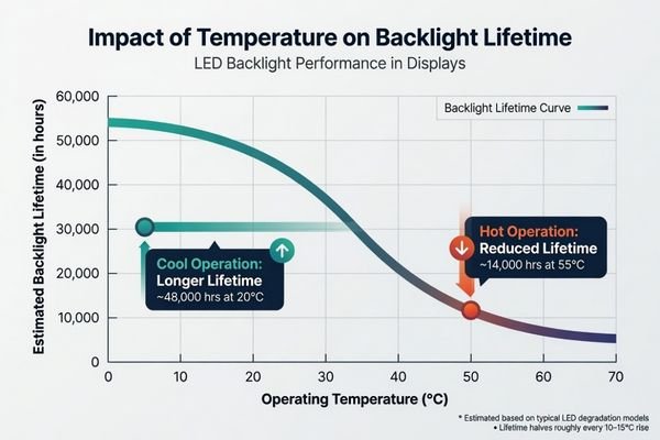
Backlight lifetime is not a fixed number that applies to every product. It depends on the brightness target, LED current, operating temperature, duty cycle, dimming strategy, and daily operating hours. Higher brightness does not automatically mean poor lifetime, but high current and high temperature together can increase stress.
Backlight lifetime should be reviewed against the actual use profile. A module running at high brightness for long hours in a sealed enclosure faces a different stress condition from one used intermittently or with adaptive dimming.
| Factor | What to Review | Possible Impact |
|---|---|---|
| Operating Temperature | LED, driver, module, and enclosure temperature | Higher temperature may accelerate lumen degradation3 |
| Driving Current | Backlight current at target brightness | Higher current increases electrical and thermal stress |
| Duty Cycle | Daily operating hours and brightness mode | Long operation increases accumulated heat exposure |
| Dimming Strategy | PWM, ambient light control, or brightness modes | Lower average brightness can reduce thermal load |
| Enclosure Condition | Sealed, fanless, ventilated, or chassis-connected | Weak heat paths may raise module temperature |
The practical target is not to avoid high brightness. It is to make sure the brightness target, thermal path, power budget, driver strategy, and usage profile fit together. In many projects, a balanced design can support outdoor readability without pushing the backlight system harder than necessary.
Applications With Higher Thermal Risk
The same high brightness LCD module can behave very differently in different equipment. A module that works well in a ventilated structure may become risky inside a sealed outdoor terminal. A module used indoors may behave differently from one installed under direct sunlight.
Thermal risk is higher when strong backlight power, limited airflow, high ambient temperature, long duty cycle, direct sunlight, and sealed device structure appear together.
For applications such as transportation systems, marine equipment, smart terminals, outdoor kiosks, and industrial control devices, thermal behavior should be reviewed around the real installation environment.
| Application | Main Thermal Risk | What to Check |
|---|---|---|
| Outdoor kiosk | Sunlight, sealed structure, long operation | Ambient temperature, solar load, thermal path |
| Transportation equipment | Long duty cycle, vibration, limited space | Mounting, driver position, duty cycle |
| Marine equipment | Sunlight, sealing, humidity protection | Passive heat path, cover glass, brightness mode |
| Vehicle-mounted terminal | Cabin heat and sunlight through windows | Installation angle, enclosure temperature |
| Industrial sealed terminal | Fanless design and continuous use | Chassis conduction, power budget, dimming strategy |
Sealed and Fanless Enclosures
Many outdoor, industrial, and marine devices use sealed structures to protect against dust, moisture, or harsh environments. Some are also fanless to reduce moving parts and simplify maintenance.4 That can be good for reliability, but it also reduces the amount of natural airflow around the display.
In these projects, heat usually needs to leave through the LCD frame, bracket, chassis, thermal pad, or other metal structure. If the module is mechanically mounted but thermally isolated, the backlight heat may stay near the display. This can affect brightness stability even when the module itself is electrically correct.
Direct Sunlight and High Ambient Temperature
Outdoor kiosks, transportation displays, vehicle-mounted equipment, and marine devices may operate under strong sunlight and high ambient temperature. Solar load adds heat from outside, while the high brightness backlight adds heat from inside.
This combination should be checked before the brightness target and enclosure design are locked. A short indoor sample test is not enough for this kind of application, because it does not reproduce sunlight exposure, enclosure heat buildup, or long-hour operation.
Design Factors That Help Reduce Thermal Risk
Thermal risk should be reviewed at the LCD module integration level. The brightness target, backlight power, enclosure design, driver location, dimming strategy, and operating environment all influence the final result.
A reliable high brightness LCD module design needs a practical heat path. Heat may leave through the module frame, bracket, chassis, thermal contact surface, ventilation path, or surrounding mechanical structure. Driver placement and cable load also deserve attention because they can become local heat or reliability risks.
During a thermal design review, I would first separate the heat source from the heat path. The heat source may be the backlight, driver board, power circuit, or nearby electronics. The heat path may be the LCD frame, mounting bracket, chassis, thermal pad, airflow path, or enclosure wall. If these two parts do not connect well, heat stays in the wrong place.
| Thermal Review Item | Why It Matters |
|---|---|
| Brightness Target | Determines backlight power and thermal load |
| Backlight Power | Helps evaluate current, driver needs, and heat generation |
| Enclosure Condition | Sealed or fanless designs increase heat buildup risk5 |
| Thermal Path | Defines how heat leaves the LCD module area |
| Contact Surface | Affects conduction through frame, bracket, or chassis |
| Driver Placement | Can create local hot spots inside the device |
| Duty Cycle | Long-hour operation increases accumulated thermal stress |
| Dimming Strategy | Reduces average power when full brightness is not needed |
| Ambient Temperature | Affects brightness stability and backlight lifetime |
| Installation Angle | Influences sunlight exposure and surface temperature |
| Cable and Connector Load | Helps avoid stress around power and backlight connections |
Power budget and brightness control should also be checked early. PWM dimming, ambient light control, or defined brightness modes can reduce average power when full brightness is not always required. A product that runs at maximum brightness all day in a sealed enclosure needs a more conservative thermal review than a product that only uses peak brightness for short periods.
Thermal Validation Before Production
A working sample does not prove thermal stability. High brightness LCD modules may pass a short bench test and still show problems after several hours inside the final enclosure.
Thermal validation should test the LCD module inside the planned enclosure at the target brightness, expected ambient temperature, and real duty cycle. The review should look for brightness drop, driver hot spots, internal heat buildup, surface temperature, and dimming behavior before production.
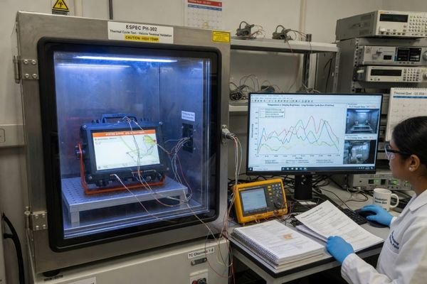
Before production, the test should be closer to the real device condition, not only a loose module on a desk. That means using the intended enclosure, target brightness setting, backlight control method, operating mode, and expected ambient temperature. This is where hidden hot spots usually become visible.
| Validation Item | What to Observe |
|---|---|
| Long-hour operation | Whether brightness remains stable after continuous running |
| Target ambient temperature | Whether the module works under expected environmental heat |
| Enclosure test | Whether heat builds up inside the real device structure |
| Driver temperature | Whether the backlight driver becomes a hot spot |
| Brightness trend | Whether luminance drops after heat accumulation |
| Dimming behavior | Whether the system reduces brightness for protection |
| Cable / connector load | Whether power connections remain stable |
| Surface temperature | Whether the front surface or module frame becomes too hot |
For sealed, fanless, outdoor, or long-hour operation devices, this validation should be completed before the module direction is finalized. The purpose is not to replace full product certification. It is to confirm whether the LCD module integration remains stable under the expected operating conditions.
Discuss your custom display project before confirming the brightness target, thermal path, and validation plan.
High Brightness LCD Thermal Management FAQ
Why do high brightness LCD modules generate more heat?
High brightness LCD modules usually need stronger LED driving and higher backlight power. More power means more heat around the module, driver area, and enclosure structure.
Does higher brightness reduce backlight lifetime?
Not by itself. The real risk appears when high brightness combines with high current, heat buildup, long operating hours, weak heat dissipation, or continuous full-brightness use.
How can thermal management improve sunlight readability?
Thermal management helps the module keep stable brightness during operation. For sunlight readable applications, stable luminance over time is often more useful than a high startup brightness number.
Are sealed outdoor devices more difficult for high brightness LCD modules?
Yes. Sealed outdoor devices usually have limited airflow and may also face direct sunlight and high ambient temperature. Passive heat paths need to be reviewed early.
Does a high brightness LCD module always need a fan?
Not always. Some projects can use passive heat transfer through the metal frame, bracket, chassis, or thermal contact surface. The answer depends on brightness target, enclosure design, ambient temperature, duty cycle, and available space.
What information is needed to review LCD module thermal design?
Useful information includes brightness target, backlight power, operating environment, ambient temperature, enclosure drawing, duty cycle, power limit, backlight control method, installation angle, and expected production plan.
Should I choose lower brightness to reduce heat?
Not necessarily. The better question is whether the required brightness can be supported by the optical structure, backlight power, thermal path, dimming strategy, and real application conditions.
Conclusion
Thermal management for high brightness LCD modules is not only about lowering temperature. It is about keeping brightness stable, protecting backlight lifetime, reducing integration risk, and confirming that the module can operate in the expected device environment.
A reliable high brightness LCD module design should balance luminance, backlight power, optical structure, heat path, dimming strategy, duty cycle, ambient temperature, and validation before production. The final device reliability still depends on the complete customer device design, but early LCD module thermal review can reduce late-stage redesign risk.
Not sure whether your high brightness LCD module can stay stable in your application? Start by preparing your brightness target, backlight power, operating environment, ambient temperature, enclosure condition, duty cycle, power limit, backlight control method, installation angle, and expected production plan.
→ Discuss your custom display project
✉️ info@lcdmodulepro.com
🌐 https://lcdmodulepro.com/
-
LED Screen Parts. “LED Screen Driving Principle Explained: Key ICs & Workflow.” ↩
-
Texas Instruments. “Overcoming Challenges for Backlight LED Drivers in Automotive Displays.” ↩
-
HARDO. “How Temperature Affects Longevity of LED Luminaires.” ↩
-
Esis. “How Fanless Industrial PCs Help Reduce Maintenance Costs.” ↩
-
DNP Group. “The Basics of Fanless Cooling Technology.” ↩