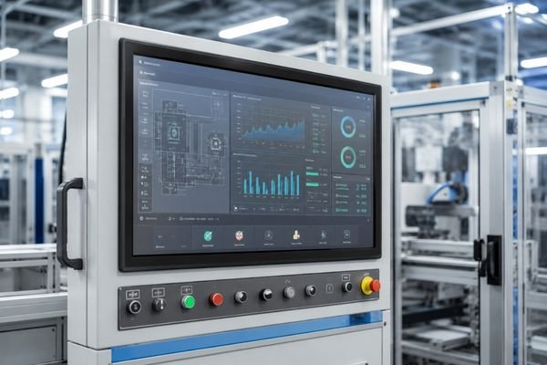
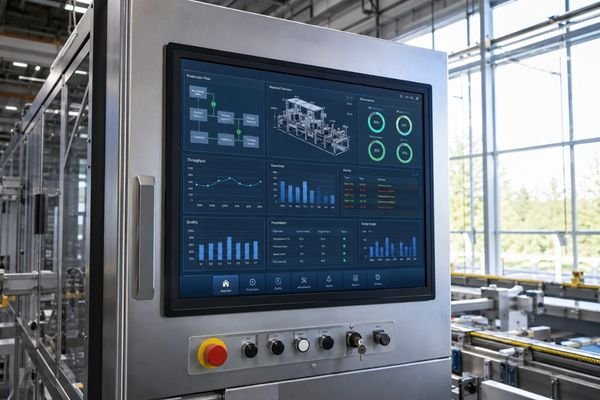
A 27-inch high brightness industrial LCD module direction for HMI panels, machine interfaces, control equipment and high ambient-light display applications.
This module direction is suitable for projects that require stronger readability, optical bonding, cover glass coordination, interface matching and mechanical integration support.
It is not only a brighter screen option. The final display module should be evaluated together with brightness target, reflection control, touch or cover glass structure, mounting space, interface path and production planning.
A 27-inch high brightness LCD module should be reviewed as a complete display path. Brightness, optical bonding, cover glass, interface, mounting structure and operating environment all affect whether the module can perform reliably after equipment integration.
27-inch industrial LCD module for HMI panels, machine interfaces and equipment display systems.
Reviewed according to ambient light, viewing distance, installation angle and readability expectation.
Used to improve contrast stability, reduce internal reflection and support stronger front-surface readability.
Can be reviewed with thickness, surface treatment, durability, printing area and touch integration requirements.
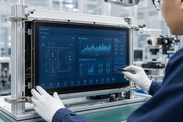
Interface, connector direction, mounting structure and enclosure fit should be confirmed before sampling.
If these conditions match your project, brightness alone is not enough. The module should be evaluated together with optical bonding, surface treatment, enclosure design and long-term supply planning.
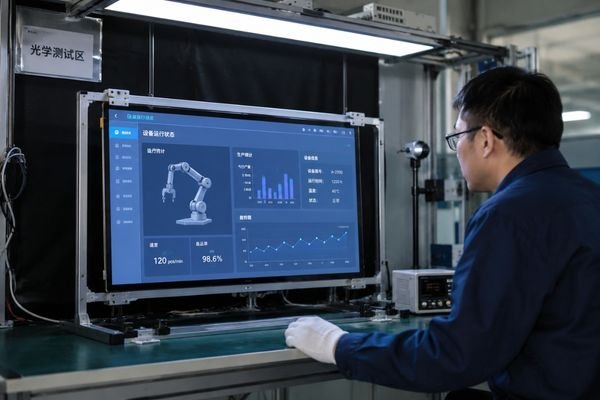
A standard indoor display may not provide enough readability when industrial equipment is used in bright workshops, window-facing locations, semi-outdoor spaces or control systems with demanding visual requirements.
A 27-inch high brightness LCD module with optical bonding is suitable when the project needs a larger HMI display area, stronger ambient-light readability, better reflection control and stable equipment-level integration.
Before sample selection, the display should be reviewed together with cover glass, touch structure, interface path, mounting method and enclosure design.
The goal is not simply to choose a brighter 27-inch LCD module, but to confirm whether brightness, optical bonding, cover glass, structure and interface can work together inside the final equipment.
This 27-inch high brightness industrial LCD module should be treated as a project-level display direction rather than a fixed stock specification. Final parameters may vary according to brightness target, optical bonding requirement, cover glass structure, interface path, mounting method and equipment-level integration conditions.
The stronger approach is to evaluate the LCD panel, backlight, optical bonding, cover glass, interface, mechanical structure and production continuity as one complete module path.
This page helps equipment teams check whether a 27-inch high brightness LCD module direction fits the real use environment before deeper sample, enclosure and production decisions begin.
| Module Direction | 27-inch industrial TFT LCD module direction for HMI panels, machine interfaces and embedded equipment displays. |
| Brightness Direction | High-brightness configuration reviewed according to ambient light, viewing distance, installation angle and readability expectation. |
| Optical Direction | Optical bonding direction for reduced internal reflection, improved contrast stability and better front-surface readability. |
| Viewing Direction | Wide-viewing display direction suitable for industrial HMI, control panels and larger equipment interface layouts. |
| Integration Path | Project-based review of cover glass, touch, interface, connector direction, mounting details and enclosure fit. |
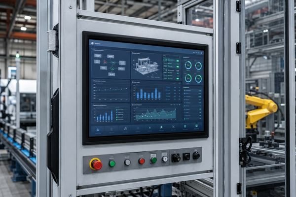
A 27-inch display area can help industrial equipment show more HMI content, machine status, process guidance and operating data. But size alone does not guarantee that users can read the screen clearly in real working conditions.
In high ambient-light environments, reflected light, internal reflection, cover glass thickness, surface treatment and installation angle can reduce perceived contrast. Optical bonding helps improve front-surface readability by reducing internal reflection and supporting a more stable viewing experience.
For project teams, the key question is whether the complete display module can remain readable, stable and practical after being integrated into the final equipment.
Check whether a standard indoor display assumption is still valid under the real lighting, viewing distance and installation angle of the equipment.
Evaluate glare, internal reflection, cover glass, surface treatment and bonding direction before sample validation.
Confirm interface, touch, mounting, enclosure space and front-surface structure before the mechanical design becomes fixed.
For a 27-inch high brightness industrial LCD module project, customization should be reviewed as a complete integration path, not as isolated parameter changes. The following items usually need to be confirmed before sample selection.
| Customization Area | What Can Be Reviewed | Project Value |
|---|---|---|
| Brightness | Brightness target, ambient light, viewing distance and installation angle. | Helps confirm real readability before sample testing and equipment deployment. |
| Optical Bonding | Bonding method, reflection control, contrast stability and surface readability. | Reduces visual uncertainty in bright or reflection-sensitive environments. |
| Cover Glass | Glass thickness, AG/AR treatment, printing area, durability and touch structure. | Improves front-surface protection, usability and optical performance. |
| Interface Path | Signal source, controller board, connector direction, and system architecture. | Reduces electrical mismatch and integration uncertainty during development. |
| Mechanical Structure | Module thickness, frame direction, bezel fit, enclosure space and stack design. | Reduces late-stage mechanical redesign before device structure is fixed. |
| Mounting Details | Mounting holes, brackets, installation direction and assembly constraints. | Supports smoother equipment assembly and more predictable production planning. |
This 27-inch high brightness LCD module direction is suitable for equipment projects where a larger display area, stronger readability and optical bonding need to be considered together.
For industrial equipment systems that need a larger HMI display area for process data, operating guidance, alarms and machine status review.
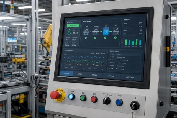
For machine control panels where readability, touch surface design, enclosure fit, interface path and mounting structure must be reviewed together.
For bright indoor, window-facing, semi-outdoor or equipment-facing locations where standard LCD readability may drop.
For embedded display systems that require optical bonding, cover glass coordination, reflection control and stable front-surface performance.
This page is not only about selecting a larger or brighter LCD module. It is about helping your team evaluate whether a 27-inch high brightness display direction can move from sample testing to practical equipment integration with fewer avoidable risks.
Support clearer viewing in bright workshops, semi-outdoor locations or window-facing equipment environments.
Review glare, internal reflection, optical bonding, cover glass and surface treatment before they become usability problems.
Clarify brightness target, interface path, bonding need and mechanical structure during early project evaluation.
Create a more stable route from sample testing to pilot review, configuration confirmation and long-term supply planning.
For equipment manufacturers, the key question is not only whether a 27-inch high brightness LCD module is available. What matters is whether readability target, optical bonding strategy, cover glass, interface path, mechanical structure and long-term deployment continuity can be evaluated early enough to avoid redesign.
LCD Module Pro supports this process from early project review to sample discussion, pilot validation and production planning.
Evaluate brightness, optical bonding, cover glass treatment and ambient-light conditions as one practical display direction.
Review interface, structure, mounting, touch or cover glass and enclosure fit before late-stage redesign becomes expensive.
Support a clearer route from early sample review to pilot validation, configuration confirmation and production planning.
These questions help clarify whether this 27-inch high brightness LCD module direction is suitable for your equipment project.
No. This page represents a 27-inch high brightness industrial LCD module direction. Final specifications may vary according to brightness target, optical bonding, cover glass, interface, structure, mounting details and integration requirements.
Not always. Optical bonding should be evaluated according to ambient-light condition, reflection target, cover glass design, touch structure and the final equipment use environment.
No. It can also be suitable for bright indoor, semi-outdoor, window-facing or high-ambient-light industrial environments where standard display readability may drop.
Yes. Brightness direction, cover glass thickness, AG/AR surface treatment, touch structure, printing area and mounting details can be reviewed according to the project.
Typical applications include industrial HMI panels, machine control interfaces, embedded equipment displays, semi-outdoor equipment and optical-demand display systems.
Interface direction should be reviewed according to the controller board and system architecture. LVDS, eDP or other project-based interface paths can be evaluated during early discussion.
Useful information includes target brightness, installation environment, interface requirement, cover glass or touch structure, mechanical drawing, mounting constraints and expected sample or production plan.
If your project requires a 27-inch high brightness industrial LCD module with optical bonding, we can help evaluate a practical direction based on your readability target, optical requirements, interface path, cover glass design, mechanical structure and production goals.
Please share your application scenario, installation environment, target brightness, interface requirement, touch or cover glass needs, mechanical constraints and sample plan. This helps us judge whether the module direction is suitable before deeper development work begins.
We will contact you within 1 working day, please pay attention to the email with the suffix “@lcdmodulepro.com”.