Power design is often underestimated in custom display projects. Equipment developers may focus first on screen size, resolution, brightness, touch function, and mechanical fit, but the display’s power architecture has a direct impact on startup stability, brightness consistency, thermal behavior, EMI risk, touch performance, and long-term reliability.
A reliable custom display module requires power design to be reviewed as part of the whole system. Input voltage, power sequencing, backlight drive current, dimming control, thermal load, electrical noise, and host system compatibility should be evaluated before the display specification is finalized.
This article focuses on module-level power design considerations for custom LCD display projects. It does not aim to replace detailed power IC design, PCB layout, or final system certification work. Instead, it helps equipment developers understand what should be confirmed before a custom display module is integrated into the final device.
For custom display projects, LCD Module Pro reviews power design together with display size, backlight requirement, interface type, touch function, mechanical structure, thermal constraints, and host system conditions. The goal is to reduce startup issues, flicker1, overheating, EMI risk, and redesign before the prototype stage moves too far.
Why Power Design Matters in Custom Display Projects
In custom LCD module integration, power design is not just a supporting function. It affects whether the display starts correctly, maintains stable brightness, avoids flicker, controls heat, and remains compatible with the host system. Many display issues that appear to be panel, interface, backlight, or touch problems may actually be related to unstable power, incorrect sequencing, insufficient current capacity, or electrical noise.
Power design is a critical system-level factor because its stability directly affects optical performance, electrical integrity, thermal behavior, touch reliability, and long-term display module operation.
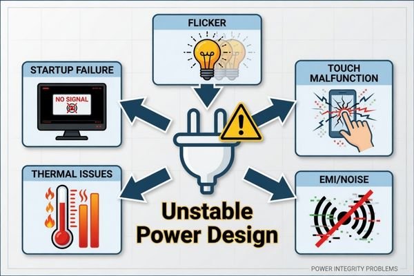
A display that turns on during a bench test may still become unstable in the final equipment if the power design is not reviewed under real operating conditions. For example, a random reset may be caused by an input voltage drop during peak current draw. Backlight flicker may come from insufficient driver stability or dimming signal mismatch. Touch malfunction may be related to electrical noise, grounding, or power coupling.
This is why power design should be reviewed early in custom LCD module engineering, not treated as a late-stage electrical adjustment. The display module, host board, cable, enclosure, and power source must be considered together.
Hidden Power Risks
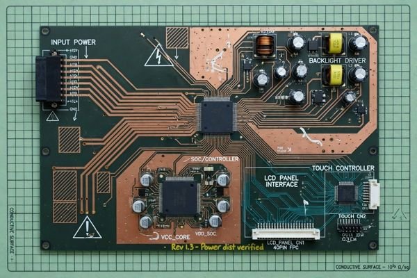
A datasheet may show a simple input voltage, but the internal display architecture can be more complex. The module may generate or manage several internal power rails for the LCD logic, panel bias, gate and source drivers, backlight driver, touch controller, and interface board. Any instability at the main input may affect these internal circuits, especially during startup, full-brightness operation, or low-temperature conditions.
Power Stability and Display Performance
The relationship between power stability and display performance is direct. Electrical noise from a DC-DC converter may interfere with data lines2. An undersized backlight driver may cause brightness fluctuation. Poor grounding may increase EMI or touch instability. Insufficient power margin may cause the display or host system to reset under load. These risks make power design a practical performance factor, not just an electrical detail.
Custom Displays Often Require More Than One Power Rail
A custom display module should not be treated as a simple single-voltage load. Modern LCD modules may require several voltage rails and power domains to support the panel, backlight, touch panel, interface, and control electronics.
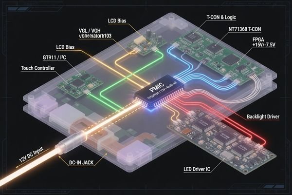
A custom display module is usually a multi-load system. LCD logic, LCD bias, VCOM, gate and source drivers, LED backlight, touch controller, interface board, and controller board may all require different power conditions.
Depending on the panel design, a TFT LCD may require logic voltage, AVDD, VGH, VGL, VCOM3, and LED backlight power rails with different voltage and timing requirements. The touch panel or interface conversion board may also require its own supply voltage. If the custom display includes a controller board, signal conversion board, or high-brightness backlight driver, the power architecture becomes even more important.
For example, a module may accept a single 12V input, while internally generating regulated voltages for logic, LCD bias, LED backlight, and touch operation. If the input power is unstable or the internal regulation is not properly matched to the load, the display may show startup issues, flicker, image abnormalities, or intermittent operation.
For custom projects, the key question is not only “What input voltage does the display use?” but also:
- What internal power rails are required?
- Which rails need tight regulation?
- Which rails must follow a specific startup sequence?
- What is the peak current during startup?
- How much power does the backlight consume at maximum brightness?
- Does the host system have enough power margin?
These questions help determine whether a standard module power design is sufficient or whether a modified or custom module-level solution is needed.
Input Voltage Range Must Match the Final Equipment
The input voltage of a custom display module must match the host system and the final equipment power architecture. Industrial equipment may use 5V, 12V, 24V, or another project-specific voltage, and some applications may require a wider input range due to unstable supply conditions.
The display module input voltage range, current capacity, power margin, cable voltage drop, and transient behavior should be confirmed early. A mismatch between the display and host power system may cause startup failure, backlight instability, or system reset issues.
Industrial equipment, transportation systems, marine devices, outdoor terminals, and embedded control products may all have different power architectures. A display that works on a test bench with a stable short cable may behave differently in the final installation with longer cable runs, shared power lines, voltage drop4, or transient events.
Important input power factors include:
- nominal input voltage
- minimum and maximum operating voltage
- startup current
- peak backlight current
- cable voltage drop
- host power supply capacity
- transient voltage behavior
- connector current rating
- grounding strategy
- available power margin
In vehicle, transportation, mobile, or outdoor equipment, the nominal voltage may experience drops, spikes, or transient events. The display module does not always need to solve every system-level power issue alone, but its input design should match the real electrical environment of the final device.
Early confirmation of input voltage conditions helps prevent a common problem: a display module that works in the lab but becomes unstable in the final equipment.
LCD Bias and Power Sequencing Affect Panel Startup
A TFT LCD panel may require specific bias voltages and startup or shutdown timing to operate correctly. Logic voltage, AVDD, VGH, VGL, VCOM, and other panel-related rails should follow the requirements of the selected LCD panel.
Power sequencing should follow the LCD panel datasheet because incorrect startup or shutdown timing may cause display abnormalities, flicker, residual images, unstable operation, or reliability risks.
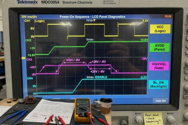
Power sequencing is especially important when a display module uses a custom controller board, interface board, or power board. If the logic voltage, LCD bias rails, and backlight enable signal are not coordinated correctly, the panel may start in an unstable state.
Possible symptoms of incorrect sequencing include:
- no image during startup
- white screen or abnormal image
- flicker during power-on
- residual image
- unstable display behavior
- panel stress during repeated startup
- inconsistent operation across temperature conditions
In a custom display power design, sequencing should be checked against the panel datasheet and the final system startup behavior. This includes power-up timing, power-down timing, reset signals, backlight enable timing, and host interface readiness.
For projects involving custom controller boards or modified LCD modules, an early module-level engineering review can help confirm whether the panel, power board, and host system startup behavior are compatible.
Backlight Power Design Is Critical for High-Brightness Displays
In high-brightness custom displays, the LED backlight is usually the largest power load and one of the main sources of heat. Its power design affects brightness stability, dimming behavior, efficiency, thermal performance, and backlight lifetime.
For high-brightness displays, the backlight driver should be treated as a critical power and control system. Backlight current, driver efficiency, dimming range, thermal path, and protection design all affect the final display performance.
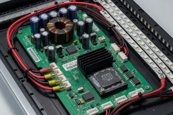
For outdoor, marine, transportation, kiosk, and industrial terminal applications, the backlight may need to deliver high luminance for long operating periods. Higher brightness usually requires higher LED current and greater power capacity, which increases thermal load and may create additional EMI or reliability challenges.
For high brightness LCD modules, backlight design should confirm:
- target brightness
- LED string configuration
- backlight current
- driver voltage range
- dimming control method
- driver efficiency
- power margin
- startup inrush behavior
- open/short protection
- thermal path
- expected backlight lifetime
LCD Module Pro typically reviews brightness target, backlight current, driver method, thermal path, enclosure constraints, and operating environment together before recommending a display module configuration. This helps avoid selecting a display that meets the brightness target on paper but creates heat, flicker, or lifetime issues in the final equipment.
Dimming Control Can Affect Flicker, EMI, and User Experience
Backlight dimming is not only a brightness control function. The dimming method can influence visible flicker, low-brightness behavior, camera compatibility, EMI performance, control interface design, and user comfort.
PWM dimming, analog dimming, and hybrid dimming each have different trade-offs. The right dimming method should be selected according to the application environment, brightness range, control signal, EMI target, and user interaction conditions.
PWM dimming controls average brightness by switching LED current on and off rapidly. It can provide a wide dimming range and good efficiency, but low PWM frequency or unsuitable control settings may create visible flicker or camera banding. Analog dimming adjusts LED current directly, which may reduce flicker risk but can affect color or brightness behavior at low current levels. Hybrid dimming combines current control and PWM control depending on driver design and brightness range.
| Dimming Method | How It Works | Advantages | Limitations |
|---|---|---|---|
| PWM Dimming | Controls brightness by rapidly switching LED current on and off. | High efficiency, wide dimming range, stable LED color behavior in many designs. | May cause visible flicker, camera banding, or EMI if not properly designed. |
| Analog Dimming | Controls brightness by adjusting LED current level. | Can reduce flicker risk and provide smooth brightness adjustment. | May affect LED color or efficiency at very low current levels. |
| Hybrid Dimming | Combines analog current control and PWM control depending on driver design and brightness range. | Can balance dimming range, flicker behavior, efficiency, and EMI performance. | More complex driver and control design. |
For equipment used with cameras, inspection systems, low-light environments, or user-facing terminals, dimming behavior should be reviewed carefully. A display that looks acceptable at full brightness may still create usability problems if low-brightness dimming causes flicker, camera banding, or unstable backlight behavior.
In custom display module projects, dimming control should be confirmed together with the host control signal, brightness adjustment range, backlight driver capability, EMI target, and expected user environment.
Power Noise, EMI, and Thermal Design Should Be Reviewed Together
Display power circuits, LED drivers, DC-DC converters, PWM dimming signals, long cables, and high-speed display interfaces may introduce power noise and EMI risks. At the same time, power conversion losses and high backlight load generate heat.
Power noise, EMI, and thermal behavior should be reviewed together because they are closely connected in a compact custom display module. A design change in one area may affect electrical stability, image quality, heat, or system validation.
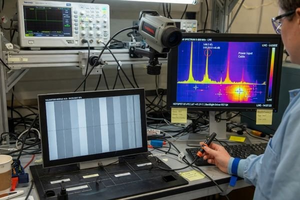
DC-DC converters used to generate internal voltage rails can produce switching noise. LED drivers and PWM dimming signals may also introduce EMI if layout, grounding, cable routing, or filtering are not handled properly. In some cases, power noise can couple into LVDS, eDP, HDMI, MIPI, or other display interface signals, causing image instability, visible artifacts, or intermittent operation.
Thermal design is connected to power design because every efficiency loss becomes heat. Backlight power, driver losses, controller board power, and surrounding electronics can all raise the internal temperature of the module and enclosure. If the thermal path is weak, the display may suffer from brightness reduction, shorter LED lifetime, unstable operation, or reduced reliability.
During custom display engineering evaluation, the following factors should be reviewed together:
- input power architecture
- DC-DC converter location
- backlight driver placement
- grounding strategy
- filtering requirements
- cable length
- connector type
- shielded cable requirement
- interface type
- enclosure material
- available heat transfer path
- operating temperature
- EMI or certification target
LCD Module Pro can support power, EMI, and thermal review at the module level by checking the display interface, cable conditions, power load, grounding constraints, enclosure space, and heat dissipation path before the display module direction is finalized.
Protection Design Reduces Field Failure Risk
A custom display module should be designed according to the electrical risks of the final application environment. Depending on the equipment type, the power source may face voltage fluctuation, incorrect connection, overload, surge, high temperature, or LED backlight fault conditions.
Protection design helps reduce field failure risk, but the protection strategy should match the final equipment environment. Some protection functions may be implemented inside the display module, while others may be handled at the host system, power input, or final equipment level.
Electrical protection may include:
- Overvoltage Protection (OVP): Helps protect against input voltage spikes.
- Undervoltage Lockout (UVLO): Prevents unstable operation when input voltage is too low.
- Overcurrent Protection (OCP): Helps protect against excessive current draw.
- Short-Circuit Protection: Reduces damage risk during output or load faults.
- Reverse Polarity Protection: Helps prevent damage from incorrect power connection where required.
- Thermal Protection: Reduces risk when temperature exceeds safe operating limits.
- LED Open Protection: Protects the backlight driver when an LED string is open.
- LED Short Protection: Protects the driver and system when an LED string is shorted.
Not every display project needs the same protection design. A desktop indoor device, outdoor terminal, industrial controller, transportation system, or marine equipment may have different electrical risks. The right protection level should be decided based on the input power source, installation environment, expected reliability, maintenance conditions, and certification requirements.
Protection design should be reviewed as part of the full power architecture, not added only after field failures appear.
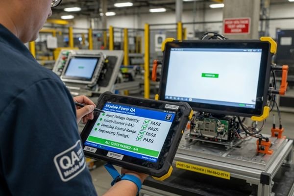
What to Confirm Before Finalizing a Custom Display Power Design
Finalizing the power design is a key milestone in a custom display project. Before the display specification, controller board, host interface, enclosure, or prototype structure is locked, the power requirements should be reviewed against the actual equipment conditions.
A custom display power design should be confirmed through a structured engineering checklist. This helps determine whether the project can use a standard power design, a modified power board, or a custom module-level solution.
| Item to Confirm | Why It Matters | Typical Project Risk |
|---|---|---|
| Input Voltage Range | Ensures the module matches the host power architecture. | Startup failure, reset, unstable operation. |
| Maximum Power Consumption | Confirms whether the host system has enough power budget. | Host overload, voltage drop, power instability. |
| Backlight Current | Affects brightness, heat, and LED lifetime. | Flicker, overheating, reduced backlight life. |
| Dimming Method | Affects brightness control, flicker, EMI, and user experience. | Visible flicker, camera banding, control mismatch. |
| Power Sequencing | Ensures LCD rails start and shut down correctly. | No image, abnormal display, residual image, reliability risk. |
| Interface Voltage Level | Ensures compatibility with host board and controller. | Interface failure, unstable image, signal mismatch. |
| Touch Power Requirement | Ensures touch controller stability. | False touch, poor sensitivity, touch malfunction. |
| Cable Length | Affects voltage drop, noise, and EMI behavior. | Unstable startup, noise coupling, intermittent failure. |
| Operating Temperature | Defines power and thermal limits. | Overheating, brightness drop, component stress. |
| Thermal Constraints | Confirms whether heat can be transferred away. | Backlight aging, hot spots, thermal shutdown. |
| EMI Requirements | Supports system validation and certification planning. | Failed EMC testing, redesign delay. |
| Host Power Capacity | Confirms the system can support peak load. | System reset, voltage dip, unstable operation. |
| Certification Plan | Aligns power design with final equipment requirements. | Late-stage redesign or validation delay. |
| Lifecycle Expectations | Supports long-term production and replacement planning. | Supply risk, redesign, compatibility changes. |
When reviewing a custom display module project, LCD Module Pro usually starts from the application environment, input voltage, brightness target, interface type, touch requirement, cable conditions, thermal limits, host power capacity, and lifecycle expectation before recommending a standard, modified, or custom module solution.
If the project is still in the early selection stage, it may also be useful to compare available industrial LCD module options before deciding whether a standard display module or a customized solution is more suitable.
Common Questions About Custom Display Power Design
What power supply is needed for a custom LCD display?
The required power supply depends on the LCD panel, backlight, touch panel, controller board, interface type, brightness target, and final equipment power architecture. It cannot be defined by a single fixed voltage without reviewing the full module configuration.
Why is power sequencing important for TFT LCD modules?
Power sequencing is important because the LCD panel may require different voltage rails to turn on and off in a specific order. Incorrect sequencing may cause abnormal display behavior, flicker, residual images, unstable operation, or reliability risks.
What causes flicker in LCD backlight power design?
Backlight flicker may be caused by PWM dimming behavior, unstable input power, insufficient driver design, low-brightness control limits, electrical noise, or poor compatibility between the dimming signal and the backlight driver.
How does high brightness affect display power design?
Higher brightness usually requires higher backlight current and greater power capacity, which increases heat and may raise EMI, driver efficiency, power margin, and backlight lifetime concerns. High brightness should therefore be reviewed together with thermal and electrical design.
What information is needed to review a custom display power design?
A power design review usually requires input voltage, brightness target, backlight current, dimming method, interface type, touch requirement, cable length, operating temperature, host power capacity, EMI requirements, certification plan, and lifecycle expectations. These details help the engineering team evaluate whether a standard, modified, or custom display module design is more suitable.
Reliable Custom Display Power Design Starts with Early Engineering Review
Reliable custom display power design should be reviewed before the display specification, host board, enclosure, and prototype structure are locked. Input voltage, LCD bias, power sequencing, backlight driver, dimming control, EMI, protection, thermal path, connector definition, and host system constraints should be evaluated together.
For equipment manufacturers, early power design review can reduce startup issues, flicker, overheating, EMI risk, validation delay, and redesign. It also helps confirm whether the custom display module can match the final equipment power architecture and operating environment.
LCD Module Pro supports custom display projects through module-level engineering evaluation, including input voltage review, backlight power assessment, dimming control review, power sequencing check, interface matching, thermal review, EMI-related design discussion, and long-term module planning.
Need a power review for a custom display module?
Share your input voltage, brightness target, backlight control method, interface type, touch requirement, cable length, operating temperature, and host system constraints with our engineering team.
Start Your Custom Display Power Review
✉️ info@lcdmodulepro.com
🌐 https://lcdmodulepro.com/
-
"What are the possible causes of image flickering in LCD displays …", https://www.quora.com/What-are-the-possible-causes-of-image-flickering-in-LCD-displays-Could-it-be-due-to-a-faulty-power-supply-backlighting-issues-or-something-else-entirely. Technical discussions note that unstable power supply or improper driving conditions can contribute to LCD flicker. This supports the need for stable voltage regulation and proper power sequencing. Scope note: Actual causes depend on panel type, driver IC, and system design. ↩
-
"EMI Suppression with Switching Frequency Modulated dc-dc …", https://ui.adsabs.harvard.edu/abs/1999IIAM….5f..27V/abstract. Research on DC-DC converters shows that switching noise can affect nearby circuits and signal lines. This supports the claim that converter noise may interfere with display data transmission. Scope note: Impact depends on converter topology, PCB layout, shielding, and grounding. ↩
-
"Common VGH, VGL, VCOM and AVDD voltage levels – PCB Artists", https://pcbartists.com/design/power-supply/vgh-vgl-vcom-avdd-voltage-generation-schematic-tft-lcd?desktop_view=show&srsltid=AfmBOoqDXQcZZONXEFV1AtmFLMvk5RQGZUwQoMWd-dxT9iXmvy58a_yP. This technical reference explains common TFT LCD voltage rails such as AVDD, VGH, VGL, VCOM, and backlight power. This supports the point that LCD modules may require multiple voltage rails with different timing requirements. Scope note: Exact rail requirements vary by panel and driver design. ↩
-
"Voltage drop – Wikipedia", https://en.wikipedia.org/wiki/Voltage_drop. This source explains how cable resistance can cause voltage drop over longer runs. This supports the point that a display may behave differently in final installation than on a short test-bench cable. Scope note: Voltage loss depends on cable length, gauge, material, current, and installation conditions. ↩