
In custom LCD module engineering, the first sample should not be based only on a preferred size, a resolution target, or a preliminary quotation request. A custom LCD module sample needs confirmed engineering inputs before sample planning begins. These inputs include mechanical fit, interface compatibility, touch structure, optical requirements, power conditions, thermal limits, and sample validation expectations.
A pre-sampling design review is an engineering checkpoint used to confirm whether a custom LCD module requirement is ready for sample planning. It helps OEM teams reduce the risk of building a first sample based on incomplete assumptions about the final equipment.
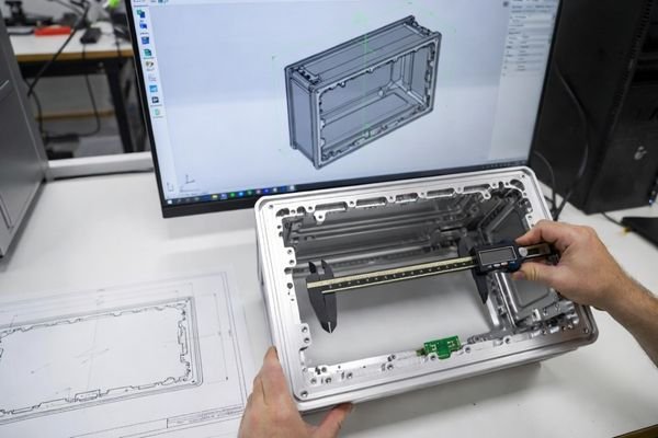
In many custom LCD module projects, repeated sample revisions are caused by incomplete alignment between the display specification and the real constraints of the host equipment1. A sample may power on successfully but still fail to support practical evaluation if the cable direction, connector position, cover glass structure, interface path, or mounting space does not match the final device.
This article explains what OEM engineering teams should confirm before custom LCD module sampling begins. The focus is not a complete project workflow, a basic RFQ form, or a pilot-production approval checklist. The focus is the design review gate before sampling, where unclear requirements are converted into confirmed engineering inputs for the first custom LCD module sample.
Why Pre-Sampling Design Review Matters in Custom LCD Module Projects
A pre-sampling design review helps determine whether the custom LCD module specification is clear enough to move into sample planning. Without this step, the first sample may be based on assumptions about mechanical dimensions, signal interface, cable routing, brightness, touch behavior, or validation criteria.
Pre-sampling design review reduces sample revision risk by confirming the display module requirement against the final equipment structure, host system, front-surface design, and application environment before hardware is built.
Beyond the datasheet
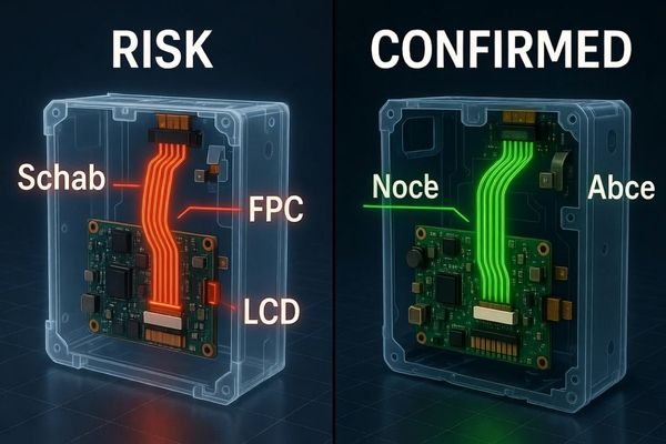
A display datasheet can provide panel size, resolution, interface type, brightness, and electrical parameters. However, it does not fully describe how the module will fit inside an OEM device. It does not confirm front-panel opening, FPC direction, connector clearance, cable bend radius, touch stack behavior, thermal space, or how the sample will be evaluated inside the final equipment.
Cross-functional alignment
A pre-sampling review also helps align different OEM teams before the supplier builds the first sample. Mechanical engineers review enclosure fit and mounting space. Hardware engineers confirm interface, power, connector, and signal compatibility. Product managers or system engineers confirm user environment, brightness, touch interaction, and validation expectations. This alignment helps avoid a sample that satisfies one requirement while creating a problem in another area.
Confirm the Application Requirement Before Freezing the Display Direction
The display direction should be based on the final equipment environment, not only on the preferred display size. A display used in an indoor industrial control panel has different requirements from one used in an outdoor payment terminal, transportation console, embedded machine interface, or semi-outdoor service terminal.
Application requirements define the display direction before sampling. OEM teams should confirm where the display will be used, how users will interact with it, what information the HMI needs to show, and what operating conditions the module must support.
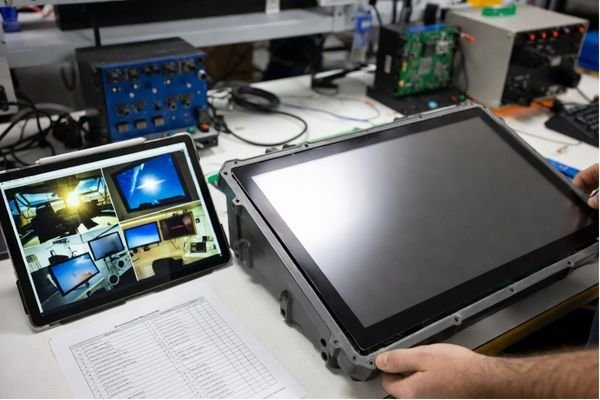
A practical design review usually starts with the application context. Important questions include whether the equipment is indoor, outdoor, semi-outdoor, vehicle-mounted, handheld, wall-mounted, or embedded into a machine. The team should also confirm whether operators use gloves, whether the display is exposed to vibration, whether the equipment has limited internal space, and whether the product needs long-term supply stability.
These application factors influence display size, brightness, operating temperature, touch structure, cover glass design, interface selection, cable direction, component availability, and sample validation. Freezing a display direction based only on diagonal size and resolution may lead to a sample that looks suitable on paper but does not match the actual equipment conditions.
Before sample planning, OEM teams should also confirm whether the requirement can be met by existing industrial LCD modules or whether the project needs a modified or fully custom LCD module direction.
Review Mechanical Fit, Active Area, and Equipment-Level Constraints
Mechanical review before sampling should include more than diagonal size. A custom LCD module must match the final equipment structure, front-panel opening, mounting method, internal space, connector clearance, and assembly process.
A drawing-based mechanical integration for LCD modules review helps confirm outline dimensions, active area position, viewing area, mounting points, thickness, FPC direction, cable routing, and enclosure fit before sample planning.
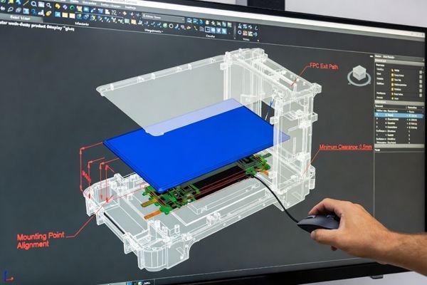
A sample that meets the electrical specification can still be difficult to evaluate if it cannot fit the equipment enclosure. The module may be too thick, the connector may interfere with the mainboard, the cable may exit in the wrong direction, or the active area may not align with the front-panel window.
| Mechanical Checkpoint | What OEM Teams Should Confirm | Common Risk if Not Reviewed |
|---|---|---|
| Outline dimensions | Complete X, Y, and Z dimensions of the LCD module, including cover glass, frame, bracket, and connector height | The module may be too large or too thick for the enclosure |
| Active area and viewing area | Alignment between AA, VA, cover glass opening, and front-panel window | The bezel may cover part of the active display or expose unwanted gaps |
| Mounting structure | Screw holes, brackets, alignment pins, frame design, and assembly method | The module may not mount securely or may require enclosure changes |
| FPC and cable direction | Cable exit direction, cable length, bend radius, and routing path | The cable may conflict with internal components or be too difficult to assemble |
| Connector position | Connector location, orientation, height, and clearance from the host board | Connector interference may prevent assembly or require board changes |
| Internal equipment space | Clearance around the LCD module, controller board, cable, and mechanical parts | The module may fit on the drawing but fail during real assembly |
This review should be done before the first custom LCD module sample is built2. If mechanical conflicts are found after sampling, the project may require new drawings, new cables, different connector positions, or a revised sample build.
Confirm Interface, Signal Path, and Host System Compatibility
A display sample that fits mechanically still needs to communicate correctly with the host system. Interface review before sampling helps confirm whether the display module, controller board, cable, connector, power input, and control signals are compatible with the OEM device.
Interface compatibility should be reviewed at the signal, connector, pin-definition, cable, and host-system level. Early display interface customization review helps reduce the risk of sample-level connection or power-on issues.
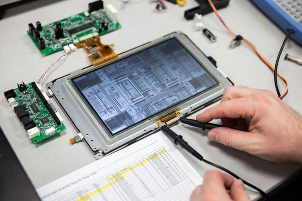
Interface confirmation should go beyond simply naming the interface type. For LVDS, eDP, MIPI, RGB, HDMI, DP, or other interfaces, the OEM and supplier teams should confirm data lane configuration, signal timing, voltage level, connector type, pin definition, cable length, shielding needs, and host board compatibility.
If a controller board or interface conversion board is required, the review should define how it will be powered, where it will be installed, how it will connect to the host system, and whether firmware or OSD behavior needs to be adjusted. Power input, backlight enable, dimming control, reset signals, and other control functions should also be confirmed before sampling.
This step helps avoid a common first-sample problem: the module is physically correct, but the host system cannot drive it properly. A clear interface path makes the first sample easier to power on, test, and evaluate.
Evaluate Touch, Cover Glass, and Front-Surface Stack Requirements
Touch should be reviewed as part of the full front-surface structure, not only as a yes-or-no function. A touch-enabled display module may include an LCD panel, touch sensor, cover glass, bonding layer, surface treatment, printed border, front panel, and enclosure structure.
For touch-enabled projects, touch integration for LCD display modules should be reviewed together with cover glass thickness, bonding method, touch controller tuning, glove operation, wet touch, water droplet interference, and front-panel structure.
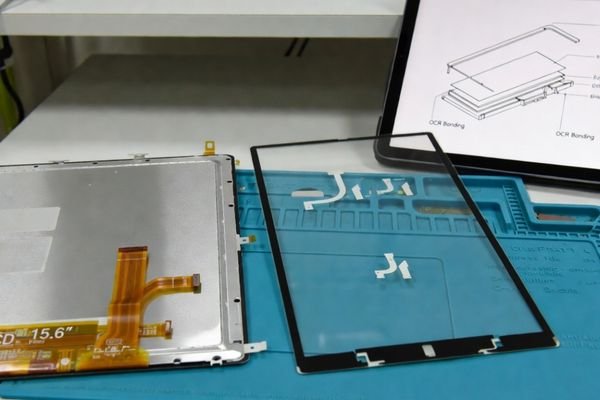
OEM teams should confirm whether the project requires PCAP touch, resistive touch, multi-touch, glove operation, wet touch, false touch control, or special touch behavior under environmental conditions. These requirements affect touch sensor selection, controller tuning, cover glass thickness, and validation planning.
Cover glass also needs careful review before sampling. The team should confirm glass thickness, material, shape, edge treatment, printing, hole position, surface treatment, and whether optical bonding is required. If bonding is needed, the bonding method, such as OCA or OCR, should be reviewed at a project level without turning the sampling review into a detailed bonding-process discussion.
A touch solution that works on an open test bench may behave differently after cover glass, bonding, front-panel material, enclosure grounding, or environmental conditions are added. This is why the front-surface stack should be reviewed before the first sample is built.
Align Brightness, Optical Performance, Power, and Thermal Conditions
Brightness should be defined according to the real operating environment instead of being requested as a generic high-brightness specification. Brightness, optical performance, power consumption, and thermal behavior are connected, especially in high-brightness or enclosed equipment.
OEM teams should review brightness target, ambient light, glare, cover glass reflection, optical bonding need, backlight power, input voltage, dimming method, operating temperature, and enclosure heat before custom LCD module sampling begins.
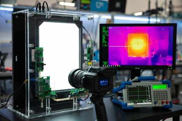
A brightness target should be based on actual operating conditions. Indoor equipment, outdoor terminals, semi-outdoor systems, machine panels near strong lighting, and vehicle-mounted displays may have very different readability requirements. The review should also consider viewing angle, cover glass reflection, surface treatment, and whether optical bonding or anti-glare treatment may be required.3
Higher brightness usually increases backlight power and heat. Before sampling, the OEM team should confirm whether the host system can provide the required input voltage and power margin, whether dimming control is compatible, and whether the enclosure can manage the heat generated by the LCD module.
If these factors are not aligned before sampling, the first sample may be too dim, consume more power than expected, become thermally unstable inside the equipment, or require another backlight and power design review.
Define Sample Validation Inputs Before the First Module Is Built
The purpose of the first custom LCD module sample is to support practical evaluation. For that evaluation to be useful, the acceptance inputs should be defined before the sample is built.
Sample validation inputs should be confirmed before sample production so the first module can be judged against clear technical expectations instead of subjective impressions. This is not a pilot-production approval checklist; it is the pre-sampling input needed to make later sample evaluation more objective.
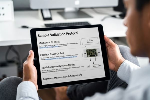
OEM teams should confirm which drawings, specifications, interface definitions, and evaluation items will be used when the sample arrives. The sample should be built against agreed technical inputs, including mechanical outline, active area, interface pinout, power input, cable direction, touch stack, cover glass structure, brightness target, operating environment, and special validation requirements.
This does not need to become a full documentation package at the sampling stage. The key is to define what “acceptable for evaluation” means. For example, the OEM team may need to check whether the module fits the enclosure, whether the host board can drive the display, whether touch works through the cover glass, whether brightness is sufficient under expected lighting, and whether the cable routing works during assembly.
Clear validation inputs make sample feedback more useful. Instead of saying that the sample “does not feel right,” the OEM team can identify specific issues such as connector clearance, touch response, viewing area alignment, brightness, thermal behavior, or interface stability.
Pre-Sampling Design Review Checklist for OEM Engineering Teams
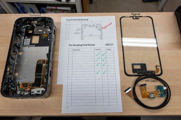
A checklist helps OEM engineering teams determine whether a custom LCD module project is ready for sample planning. It also helps separate confirmed requirements from open questions that need clarification before hardware is built.
A pre-sampling checklist formalizes the design review gate. It confirms whether application, mechanical, interface, touch, optical, power, thermal, lifecycle, and validation inputs are clear enough to support a practical custom LCD module sample.
| Review Area | What OEM Teams Should Confirm | Why It Matters Before Sampling |
|---|---|---|
| Application environment | Indoor, outdoor, semi-outdoor, embedded use, operator workflow, lifecycle expectation | Defines brightness, touch, temperature, optical, and validation direction |
| Display size and area | Diagonal size, resolution, AA, VA, cover glass opening, front-panel window | Prevents display area mismatch and poor front-panel alignment |
| Mechanical fit | Outline, thickness, mounting points, bracket, enclosure space, assembly sequence | Reduces enclosure interference and sample fit problems |
| FPC and cable path | FPC direction, cable length, bend radius, connector clearance, internal routing | Prevents cable conflict and assembly difficulty4 |
| Interface and host system | LVDS, eDP, MIPI, RGB, HDMI, DP, pinout, connector, controller board, signal timing | Reduces power-on failure and host compatibility risk |
| Power input and control | Input voltage, backlight power, enable signal, dimming method, power margin | Helps align the sample with host power capability |
| Touch and front surface | PCAP or resistive touch, cover glass, bonding, glove touch, wet touch, false touch control | Reduces touch performance and front-surface integration problems |
| Optical requirement | Brightness target, ambient light, glare, viewing angle, optical bonding or AG/AR need | Helps avoid readability problems in the real application |
| Thermal condition | Operating temperature, enclosure heat, backlight heat, heat dissipation path | Reduces brightness instability and reliability risk |
| Lifecycle and supply | Panel availability, expected product life, possible replacement direction | Helps avoid selecting a display direction with poor long-term support |
| Sample validation inputs | Drawings, specification, test items, acceptance expectations, sample purpose | Ensures the sample can be evaluated objectively |
If several items remain unclear, the project may not be ready for sampling yet. In that case, the practical next step is not necessarily to delay the project indefinitely, but to clarify the open engineering inputs before the first sample is built.
Common Questions About Custom LCD Module Design Review Before Sampling
What is a custom LCD module design review before sampling?
A custom LCD module design review before sampling is an engineering review conducted before sample production begins. It confirms whether display size, mechanical structure, interface, touch stack, brightness, power conditions, operating environment, and validation inputs are clear enough to support a practical custom LCD module sample. The goal is to make the first sample useful for equipment-level evaluation.
Why is size and resolution not enough for a custom LCD module sample?
Size and resolution only describe part of the display requirement. A sample also depends on active area, viewing area, outline dimensions, FPC direction, connector position, interface type, power input, touch stack, cover glass, brightness, thermal condition, and mechanical fit inside the final equipment. Without these inputs, the sample may not support meaningful evaluation even if the panel size is correct.
Which teams should join the pre-sampling design review?
The review usually involves hardware engineers, mechanical engineers, product managers, sourcing teams, display integration engineers, and the supplier’s engineering team. Some projects also need firmware, touch, optical, or thermal engineers. Each team confirms a different risk before the sample is built.
What problems can happen if design details are not reviewed before sampling?
Common problems include incorrect FPC direction, connector interference, interface mismatch, insufficient brightness, unstable touch performance, wrong cover glass design, thermal issues, cable routing problems, and unclear sample evaluation criteria. These issues can lead to repeated sample revisions and longer project schedules.
How does a pre-sampling review help reduce custom LCD module project risk?
A pre-sampling review reduces risk by turning unclear requirements into confirmed engineering inputs before the sample is built. It helps the supplier and OEM team align on mechanical fit, interface compatibility, touch behavior, optical performance, power conditions, thermal constraints, and validation expectations early in the project.
Better Samples Start with Clear Design Review Before Sampling
A practical custom LCD module sample starts with confirmed engineering inputs, not only a preferred size or a quick quotation request. When OEM teams review application conditions, mechanical fit, interface path, touch structure, brightness, power, thermal behavior, lifecycle expectations, and validation criteria before sampling, the first sample is more likely to match the final equipment direction.
A clear design review does not add unnecessary complexity to the project. It helps remove avoidable sample revision loops by clarifying what the supplier needs to build and what the OEM team needs to evaluate. The result is a custom LCD module sample that can be reviewed against real application, mechanical, electrical, optical, and user-interaction requirements.
Need a design review before custom LCD module sampling? Share your target size, active area, mechanical drawing, interface, cable direction, touch requirement, cover glass structure, brightness target, power input, operating environment, lifecycle expectation, and sample validation expectations. LCD Module Pro can help review whether the project inputs are clear enough for sample planning.
✉️ info@lcdmodulepro.com
🌐 https://lcdmodulepro.com/
-
"Software Prototyping: A Case Report of Refining User … – PMC", https://pmc.ncbi.nlm.nih.gov/articles/PMC4817332/. This case report shows how unclear or evolving requirements can lead to repeated prototype revisions. This supports the point that incomplete alignment between display specifications and host equipment constraints may increase sample iteration. Scope note: The source discusses software prototyping, so the LCD module application is an engineering analogy. ↩
-
"What Is Design for Manufacturing (DFM)? – Studio Red", https://www.studiored.com/blog/design/design-for-manufacturing/. This source explains that DFM reviews help identify manufacturing, assembly, and fit issues before production. This supports reviewing mechanical integration before building the first custom LCD module sample. Scope note: It covers general DFM principles, not LCD-specific design rules. ↩
-
"Optical Bonding LCD", https://displaylogic.com/film-enhancements/optical-bonding/. This source explains that optical bonding can reduce reflections and improve readability, especially in bright environments. It also supports considering anti-glare or bonding options when optical performance is critical. Scope note: Results depend on bonding material, coating quality, and application conditions. ↩
-
"How to Select a PCB Cable Assembly", https://www.protoexpress.com/kb/how-to-select-pcb-cable-assembly/. This source discusses cable assembly selection and routing considerations. It supports planning FPC and cable paths early to reduce cable conflict and assembly difficulty. Scope note: The guidance is general electronics design advice, not specific to LCD module FPC routing. ↩