In custom LCD module development, a sample that lights up is only an early milestone. It proves that the basic direction may be workable, but it does not prove that the module is ready for stable production. Before an LCD module can be used in a real device and supplied repeatedly, it needs a structured validation path.
EVT, DVT, and PVT help reduce risk in custom LCD module projects. EVT checks whether the LCD module direction is technically feasible, DVT validates the design under real application conditions, and PVT confirms whether the approved configuration can be produced consistently.
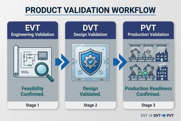
The exact boundary between EVT, DVT, and PVT1 may vary by company or project process, but the core logic is similar: find engineering risks early, close design risks before production planning, and confirm production consistency before batch supply.
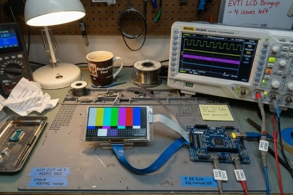
For LCD modules, validation may involve interface compatibility, timing, power, backlight control, mechanical fit, touch integration, cover glass, optical bonding, thermal behavior, EMI/ESD risk, reliability, BOM stability, and production inspection. A module that works on a bench can still fail after it is installed into a sealed enclosure, connected to the final mainboard, or produced in batches.
Why EVT/DVT/PVT Matter in Custom LCD Module Projects
Validation is what separates a working sample from a production-ready LCD module configuration. A single sample may power on in a controlled lab, but the real question is whether it can work inside the customer device, under the expected operating conditions, with stable materials and repeatable production quality.
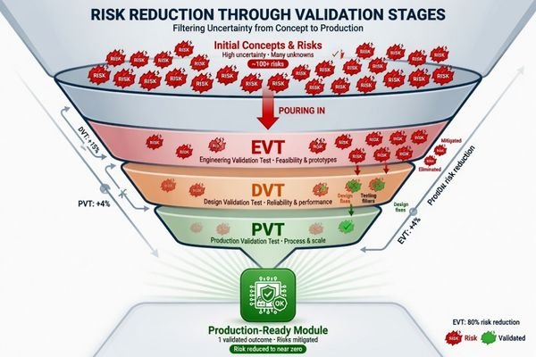
EVT, DVT, and PVT form a practical risk-reduction process. They help confirm feasibility, validate the design, and control production consistency before the project moves into stable batch supply.
In early validation planning, our engineering team usually starts by checking the application environment, interface output, mechanical constraints, brightness target, touch requirement, cover glass structure, expected quantity, and production plan before defining the EVT/DVT/PVT scope. A minor interface adaptation may need a lighter validation plan, while high brightness, touch, optical bonding, or long-term production projects usually need a more structured process.
For applications such as transportation systems, industrial control equipment, smart terminals, and outdoor kiosks, the validation plan should reflect the real operating environment. A sealed outdoor terminal may require more thermal review than an indoor control panel. A touch-integrated module may require glove, water, grounding, and EMI/ESD validation.
Not every project needs the same validation depth. The point is not to add unnecessary process, but to make sure the important risks are tested before the project becomes expensive to change.
| Stage | Key Output | Before Moving Forward |
|---|---|---|
| EVT | Feasibility confirmed | Interface, timing, power, backlight, and initial fit have no fatal issue |
| DVT | Design configuration validated | Mechanical, optical, touch, thermal, and reliability risks are reviewed |
| PVT | Production process confirmed | BOM, process, inspection, packaging, and supply plan are controlled |
Mitigating Integration and Performance Risks
Early validation is designed to expose integration risks while they are still manageable.2 Will the LCD module match the controller board timing? Can the backlight run within the available power budget? Does the FPC direction fit the enclosure? Will the touch panel remain stable after cover glass is added?
These questions should be answered before the project moves too far into enclosure tooling, firmware freeze, or volume purchasing.
Ensuring Production Consistency and Supply Stability
Later validation focuses on whether the approved LCD module can be produced consistently. This includes BOM stability, assembly repeatability, inspection standards, optical bonding process control, packaging, and lifecycle planning.
For industrial LCD module projects with multi-year product lifecycles, stable supply and repeatable quality are just as important as the first successful sample.
EVT: Proving the LCD Module Direction
EVT, or Engineering Validation Test, is the first formal validation stage in many custom LCD module projects. The main question is simple: is the selected LCD module direction technically feasible?
EVT confirms the basic feasibility of the LCD module platform, interface, timing, power, backlight, touch communication, and initial mechanical direction. It is a go/no-go checkpoint before deeper design validation begins.
During EVT, we usually focus on whether the selected LCD module direction can be technically supported by the customer’s controller board, power design, backlight requirement, and initial mechanical layout. At this stage, the goal is not to freeze every detail, but to identify fatal risks before deeper customization begins.
Typical EVT checks include:
| EVT Item | What to Check | Why It Matters |
|---|---|---|
| Interface compatibility | LVDS, eDP, MIPI, RGB, or driver board matching | Prevents basic signal mismatch |
| Resolution and timing | Pixel format, refresh rate, panel timing | Avoids flicker, no display, or unstable image |
| Power and backlight | Logic power, backlight voltage/current, PWM dimming | Confirms safe operation and brightness control |
| Touch communication | USB or I2C touch controller response | Verifies early touch direction |
| Initial mechanical fit | Outline, connector location, FPC direction | Finds early enclosure or routing conflicts |
| Brightness direction | Standard or high brightness requirement | Clarifies whether backlight customization is needed |
EVT should usually produce a clear issue list and a decision on whether the project can continue with the selected platform.3 If the application involves sunlight readability, touch integration, cover glass, optical bonding, mechanical adjustment, or interface adaptation, EVT should expose those requirements early.
Explore high brightness display modules when brightness, backlight power, optical stack, and thermal behavior need to be considered before deeper validation.
DVT: Validating Design, Reliability, and Integration Risks
DVT, or Design Validation Test, is usually the most important validation stage in a custom LCD module project. EVT proves that the direction is possible. DVT checks whether the design can meet real application requirements.
DVT validates the LCD module design against real integration, optical, thermal, touch, mechanical, electrical, and reliability requirements. It should expose design risks before tooling, pilot production, or volume purchasing begins.
During DVT, our engineering review usually moves from basic function to real application behavior. We check the optical stack, touch response, thermal load, EMI/ESD risk, cable routing, mechanical fit, cover glass structure, and reliability conditions against the actual device environment. This is where many problems that do not appear in a bench test become visible.
A strong DVT plan for LCD modules usually includes:
| DVT Item | What to Validate | Why It Matters |
|---|---|---|
| Interface stability | Timing, signal stability, driver compatibility | Prevents flicker or host compatibility failure |
| Mechanical fit | Thickness, FPC direction, connector position, mounting method | Avoids enclosure redesign or assembly interference |
| Touch integration | PCAP/resistive touch, USB/I2C, gloves, water, EMI/ESD | Reduces field touch problems |
| Optical stack | Cover glass, bonding, reflection, transmission, brightness | Confirms readability after integration |
| High brightness behavior | Backlight output, dimming, brightness stability | Supports high-ambient-light applications |
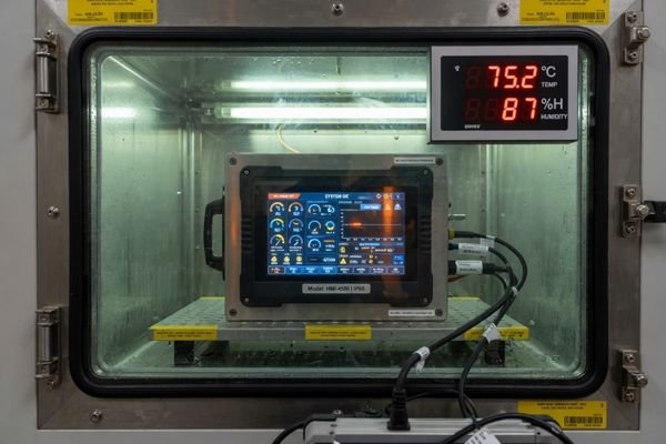
| Thermal behavior | Backlight heat, sealed enclosure, duty cycle | Helps maintain brightness and reliability |
| Reliability review | Temperature, humidity, vibration, aging, handling | Checks expected operating conditions |
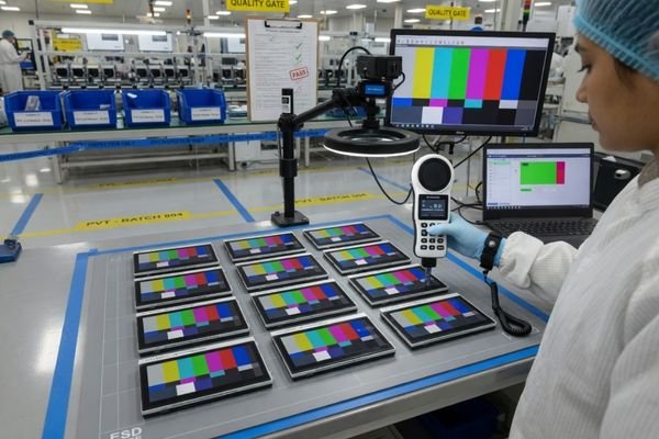
| Sample consistency | Brightness, color, touch response, tolerance | Reduces variation before production planning |
DVT samples should be close to the intended production configuration. The display structure, touch panel, cover glass, bonding method, FPC direction, connector position, backlight configuration, and mechanical design should be mature enough to test real performance.
DVT should answer one key question:
Does this LCD module design meet the application requirements under realistic operating conditions?
Discuss your custom display project before moving from prototype validation to production planning, especially when the project involves high brightness, touch, optical bonding, custom interface, or fixed enclosure space.
PVT: Preparing for Stable Production
PVT, or Production Validation Test, shifts the focus from design performance to production consistency. By the time a project enters PVT, the major design direction should already be validated. PVT is not the right stage for major redesign.
PVT verifies that the validated LCD module configuration can move into stable batch production. This stage focuses on BOM stability, assembly process, inspection methods, packaging, traceability, and supply continuity.
During PVT, we usually check whether the validated configuration can be repeated with stable materials, controlled assembly steps, inspection criteria, packaging, traceability, and supply continuity. A module that passes DVT still needs PVT review before it can be treated as production-ready.4
PVT should use production-intent materials and production-intent processes as much as possible. The goal is to confirm that the production process can repeat the design validated during DVT without adding new variation.
| PVT Item | What to Confirm |
|---|---|
| LCD panel source | Approved panel model, supply status, lifecycle risk |
| Backlight version | Brightness level, power, lifetime, dimming consistency |
| Touch sensor | Version, controller, FPC, firmware support |
| Cover glass | Thickness, printing, coating, edge treatment, tolerance |
| FPC and connector | Pinout, routing, connector availability, batch consistency |
| Optical bonding material | Adhesive type, process control, yield, reliability |
| Assembly process | Work instructions, fixtures, sequence, operator training |
| Inspection standard | Visual inspection, function test, brightness test, touch test |
| Packaging | Protection method, labeling, shipping reliability |
| Traceability | Batch record, material tracking, test record |
| Approved alternatives | Backup components for lifecycle or EOL risk |
A successful PVT run proves that the LCD module is not only technically validated, but also practical for controlled production and stable supply.
Risks of Skipping EVT, DVT, or PVT
Skipping validation may look faster at the beginning, but it often creates larger risks later. The purpose of EVT, DVT, and PVT is to find problems when corrective action is still possible.
| Skipped Stage | Common Risks That May Appear Later |
|---|---|
| Skipping EVT | Timing mismatch; interface cannot communicate; backlight power budget is wrong; touch interface does not respond; FPC direction conflicts with the enclosure |
| Skipping DVT | Backlight overheats in sealed structure; PCAP touch becomes unstable with gloves or EMI; cover glass reduces readability; cable route is compressed; reliability issues appear late |
| Skipping PVT | Bonding yield is unstable; brightness varies between batches; FPC or connector supply changes; panel EOL appears without alternatives; assembly process creates inconsistent quality |
These risks are practical. A prototype may light up successfully, but the production mainboard may not match the final timing. A housing may be tooled before connector clearance is confirmed. A touch panel may work in the lab but become unstable after the final cover glass and grounding design are added.
Validation is not about delaying the project. It is about reducing late-stage redesign, unstable assembly, and avoidable production problems.
What Equipment Teams Should Prepare Before Validation
A useful EVT/DVT/PVT process starts with clear project information. This information is not paperwork for its own sake. It helps make sure validation tests match the real application conditions5.
| Information Needed | Why It Matters |
|---|---|
| Application environment | Defines temperature, sunlight, vibration, dust, moisture, and usage conditions |
| LCD size and resolution | Confirms display platform and interface bandwidth |
| Interface type | Supports LVDS, eDP, MIPI, RGB, or driver board planning |
| Mainboard output | Helps verify timing, connector, and signal compatibility |
| Brightness target | Determines backlight, power, optical, and thermal requirements |
| Touch requirement | Defines PCAP/resistive touch, USB/I2C, glove use, and water behavior |
| Cover glass design | Affects optical stack, touch sensitivity, thickness, and assembly |
| Mechanical drawing | Helps check outline, mounting, FPC route, and connector clearance |
| Operating temperature | Guides reliability and thermal validation |
| Power limit | Helps review backlight and system power compatibility |
| Expected quantity | Supports supply planning and production validation |
| Prototype schedule | Helps plan EVT and DVT timing |
| Production plan | Helps prepare PVT, BOM stability, and supply continuity |
| Lifecycle expectation | Helps review EOL risk and alternative material planning |
If the project involves fixed mechanical space, high brightness, sunlight readability, optical bonding, PCAP or resistive touch integration, custom interface, or long-term production, early engineering review is strongly recommended.
EVT/DVT/PVT for LCD Modules FAQ
What is EVT for an LCD module?
EVT is the engineering validation stage used to confirm whether the custom LCD module direction is feasible. It usually checks basic function, interface compatibility, timing, power, backlight control, initial mechanical fit, and early touch or driver-board communication.
What is the difference between DVT and PVT for LCD modules?
DVT validates whether the LCD module design meets real application requirements, including mechanical structure, touch integration, optical performance, thermal behavior, EMI/ESD risk, and reliability. PVT verifies whether the approved design can be produced consistently with stable materials, process control, inspection standards, and supply planning.
Can an LCD module enter production after EVT?
Usually not. EVT only proves the basic direction. Before production, the project should still validate design risks and production readiness to reduce problems related to reliability, assembly, optical performance, touch behavior, and batch consistency.
What should be tested during DVT for a custom LCD module?
DVT should test mechanical fit, interface stability, brightness, readability, touch response, optical bonding, cover glass structure, cable routing, thermal behavior, EMI/ESD risk, and reliability under expected operating conditions.
When should touch and cover glass be validated?
Touch and cover glass should be reviewed during EVT if they affect the basic direction, then validated in detail during DVT before the mechanical design, optical stack, and production process are finalized.
Who should be involved in EVT/DVT/PVT for an LCD module project?
The process usually requires coordination between the LCD module team, customer hardware team, mechanical team, firmware team, purchasing team, and production planning team. This helps make sure interface, structure, firmware, supply, and production requirements are reviewed together.
What information is needed before EVT/DVT/PVT starts?
Useful information includes the application environment, LCD size, resolution, interface type, mainboard output, brightness target, touch requirement, cover glass design, mechanical drawing, operating temperature, expected quantity, and production plan.
Conclusion
EVT, DVT, and PVT help turn a custom LCD module idea into a production-ready module configuration. EVT proves the direction, DVT validates the design, and PVT confirms production consistency. For industrial LCD module projects, a sample that lights up is only the beginning.
Not sure where your LCD module project is in the validation process? Start by preparing your application, interface, mechanical drawing, brightness target, touch requirement, prototype schedule, expected quantity, and production plan. Our engineering team can help review the validation path before the module moves toward production.
→ Start your custom LCD module validation project
✉️ info@lcdmodulepro.com
🌐 https://lcdmodulepro.com/
-
OnLogic. “EVT, DVT, and PVT: Product Development Stages Explained.” ↩
-
ETA Green Power. “Early Verification Strategy: Why Testing in Product Development Matters.” ↩
-
Instrumental. “EVT, DVT, PVT Stage Gate Definitions.” ↩
-
OnLogic. “EVT, DVT, and PVT: Product Development Stages Explained.” ↩
-
GeeksforGeeks. “Requirements Validation Techniques – Software Engineering.” ↩