As an industrial equipment company expands from one product model to multiple equipment lines, display module selection often becomes fragmented. Different project teams may choose different LCD module sizes, interfaces, brightness levels, touch structures, mechanical outlines, and supply sources. Each individual choice may be reasonable for one device, but the combined result can become difficult to manage across the full equipment family.
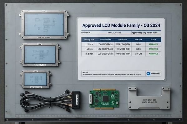
LCD module standardization is an engineering and sourcing strategy that defines a controlled set of approved display module models, specifications, and variants for reuse across multiple industrial equipment lines. The goal is not simply to reduce purchasing cost, but to improve model consistency, validation reuse, lifecycle control, and long-term equipment maintainability.
For OEM and ODM teams, uncontrolled display selection can create repeated validation work, spare parts complexity, version control issues, and long-term supply risks. A display that works well in one product may introduce problems when a similar but different model is selected for another product line. Over time, the company may need to manage too many display part numbers, too many interface variations, and too many replacement paths1.
Standardizing LCD module models does not mean forcing every device to use the same screen. In many industrial projects, it means building a controlled display model family with approved core models, approved variants, and clear rules for when a special display configuration is justified. This article explains how OEM teams can standardize LCD module models across multiple industrial equipment lines while still respecting real equipment differences.
Why LCD Module Standardization Matters for Industrial Equipment Families
When industrial equipment portfolios grow, the display module often becomes one of the hidden sources of complexity. A company may start with one device and one LCD module, then gradually add new models for different machine types, enclosure sizes, HMI layouts, brightness requirements, or customer versions. Without a controlled strategy, this can lead to model fragmentation.
LCD module standardization helps industrial equipment manufacturers reduce unnecessary display model variation, reuse part of the engineering validation basis, simplify sourcing control, and improve long-term support across equipment families.
Hidden model fragmentation risks
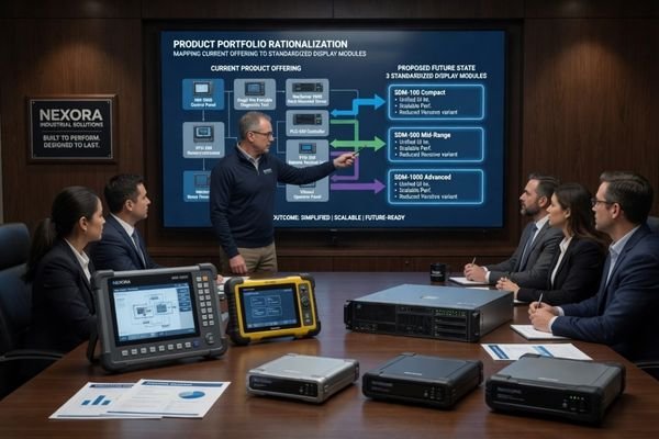
When each project team selects its own display module independently, the company may accumulate several similar but incompatible LCD modules. One product may use LVDS, another may use eDP, another may require a different connector, and another may use a different touch controller platform. These differences increase engineering work, sourcing management, manufacturing instructions, service stock, and replacement validation.
The risk is not limited to initial development. Industrial equipment often has a long product lifecycle2, and display module changes can occur due to PCN, EOL, panel availability, supplier revision updates, or customer-specific requirements. If every equipment line uses a separate display direction, each change may create a separate engineering review and replacement validation task.
Strategic value of standardization
A standardized approach gives OEM teams a more controlled display platform. Approved LCD module models can be reused across multiple equipment lines when the application requirements are compatible. Interface designs, cable direction, touch structures, brightness tiers, and validation criteria can also be aligned. This makes display integration easier to manage as the equipment portfolio grows.
Standardization is especially valuable for companies that develop multiple industrial control panels, machine interfaces, diagnostic instruments, service terminals, factory automation devices, or embedded HMI systems. Instead of treating the LCD module as a separate project-level component each time, the display becomes part of a broader equipment platform strategy.
What LCD Module Model Standardization Means
LCD module model standardization means defining a controlled display model family for multiple equipment lines. It does not always mean that every device must use one identical LCD module. That approach can be too rigid for real industrial equipment, where different products may have different enclosure space, brightness needs, touch requirements, mounting directions, and operating environments.
Effective LCD module standardization creates a controlled family of display solutions with shared rules for size range, interface, brightness tier, touch configuration, mechanical direction, validation requirements, and lifecycle management.
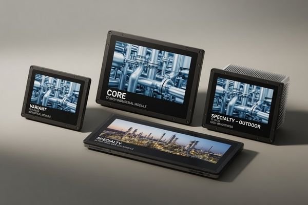
A practical standardization strategy may include several levels:
- Core standard modules: commonly used industrial LCD modules for mainstream equipment lines, such as common industrial HMI sizes and stable interface configurations.
- Approved variants: modules that share the same interface direction, similar touch platform, similar mechanical philosophy, or the same validation rules, while allowing size or brightness differences.
- Specialty modules: approved options for specific equipment needs, such as high brightness LCD modules for outdoor or semi-outdoor equipment, bar LCD modules for long HMI layouts, or square and round LCD modules for special front-panel designs.
This structure gives product teams a controlled selection range instead of an unlimited search. It also helps sourcing, engineering, and service teams understand which display models are approved, where they can be reused, and when a special display configuration requires additional review.
Identify Common Display Requirements Across Equipment Lines
Before standardizing LCD module models, OEM teams need to compare the requirements of different equipment lines. Standardization should be based on real application overlap, not on a simple wish to reduce the number of part numbers.
The first step is to identify which display requirements are common across the equipment family and which requirements must remain equipment-specific. This prevents both unnecessary model fragmentation and unrealistic over-standardization.
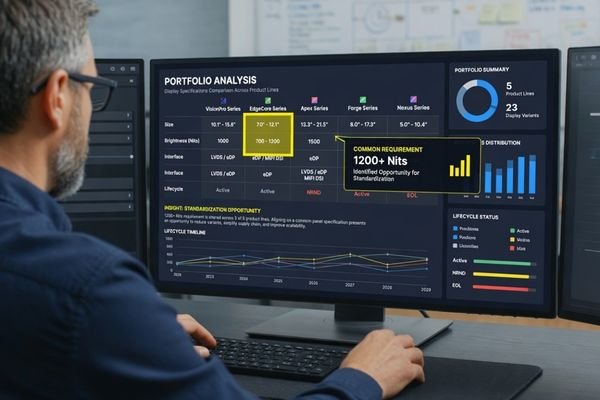
A portfolio-level review should consider the following factors:
| Review Area | What to Compare Across Equipment Lines | Why It Matters |
|---|---|---|
| Application environment | Indoor, outdoor, semi-outdoor, factory floor, vehicle-mounted, handheld, wall-mounted, or embedded use | Defines brightness, temperature, durability, and front-surface requirements |
| HMI layout | UI information density, aspect ratio, operator workflow, touch zones, alarm display, and control layout | Determines size range, resolution, and display format |
| Host platform | Mainboard family, interface availability, signal type, power output, firmware behavior, and connector strategy | Helps standardize interface and signal path |
| Mechanical space | Enclosure opening, module thickness, mounting method, FPC direction, cable routing, and connector clearance | Prevents mechanical conflicts across equipment models |
| Touch requirement | PCAP, resistive touch, no touch, glove operation, wet touch, front-panel integration, and touch tuning | Defines touch platform and cover glass strategy |
| Optical requirement | Brightness, viewing angle, glare, cover glass reflection, outdoor readability, and bonding need | Supports brightness tier planning |
| Lifecycle expectation | Expected production years, spare parts need, replacement plan, and long-term supply requirement | Supports PCN, EOL, and approved alternative planning |
The purpose of this review is to find natural grouping opportunities. For example, several equipment lines may be able to share the same size family, interface type, touch platform, or brightness tier. Other equipment lines may require special variants because of outdoor readability, narrow enclosure space, wide-format HMI layout, or a different lifecycle requirement.
A strong standardization strategy does not ignore these differences. It organizes them into a controlled model family3.
Standardize Core Specifications Without Ignoring Equipment Differences
Not every LCD module specification needs to be identical across all equipment lines. The most useful standardization usually happens at the specification areas that affect engineering reuse, sourcing control, validation planning, and long-term maintenance.
A practical LCD module standardization strategy standardizes the specifications that create the most reuse value, while allowing approved differences where equipment requirements truly diverge.
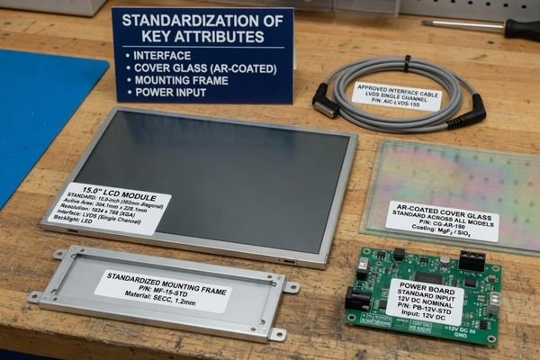
The following specification areas are usually suitable for standardization:
| Specification Area | What Can Be Standardized | Practical Value |
|---|---|---|
| Size range | Common display size families for equipment platforms | Reduces unnecessary model variation |
| Resolution family | Shared resolution levels for similar HMI layouts4 | Helps UI and software reuse |
| Interface type | LVDS, eDP, MIPI, RGB, HDMI, or DP strategy | Reduces host board and cable variation |
| Connector and cable direction | Connector location, FPC direction, cable length range, and routing path | Helps mechanical and assembly consistency |
| Brightness tier | Indoor, industrial, semi-outdoor, or sunlight-readable brightness ranges | Avoids random brightness specifications |
| Touch structure | PCAP, resistive touch, no touch, cover glass, bonding, and front-surface design rules | Reduces touch tuning and validation variation |
| Mechanical outline | Mounting method, frame direction, module thickness range, and front-panel alignment | Supports enclosure reuse and assembly planning |
| Power and dimming | Input voltage range, backlight power, enable signal, and dimming method | Helps host system compatibility |
| Operating environment | Temperature range, vibration exposure, humidity considerations, and enclosure heat | Supports reliability planning |
| Validation criteria | Module-level and equipment-level test expectations | Makes validation reuse more practical |
However, standardization should not remove necessary equipment differences. An indoor factory control panel may not need the same brightness level as a semi-outdoor service terminal. A compact instrument may have different space limits from a large machine console. A long horizontal HMI may require a bar-type LCD module rather than a standard 16:9 panel.
The right goal is controlled variation, not absolute uniformity.
Build an LCD Module Standardization Matrix for Model Control
A standardization strategy becomes more useful when it is documented. An LCD module standardization matrix helps OEM teams connect equipment lines with approved display models, shared specifications, optional variants, validation status, and lifecycle planning.
An LCD module standardization matrix turns display model control into a practical engineering and sourcing tool. It shows which LCD module models are approved, where they can be used, what differences are allowed, and what validation or replacement planning is required.
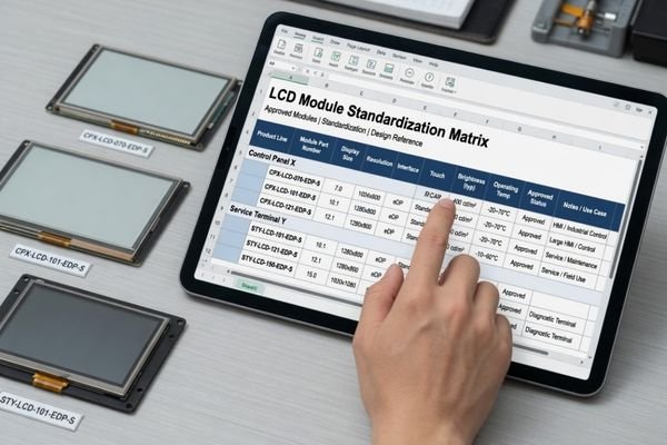
A practical matrix can be structured like this:
| Equipment Line | Approved Module Type | Size Range | Interface | Brightness Tier | Touch Option | Mechanical Direction | Validation Status | Replacement Plan |
|---|---|---|---|---|---|---|---|---|
| Indoor control panel family | Core standard industrial LCD module | Common HMI size range | LVDS or eDP | Indoor / industrial brightness | PCAP or no touch | Shared mounting and cable direction | Approved or under review | Approved alternative required |
| Semi-outdoor service terminal | High-brightness approved variant | Same or adjacent size range | Same interface direction where possible | Semi-outdoor / sunlight-readable | PCAP with cover glass | Front-panel reviewed | Equipment-level validation required | Alternate high-brightness option planned |
| Long-format machine interface | Specialty bar LCD module | Ultra-wide format | Controller board or defined interface | Application-specific | Optional touch | Custom mounting direction | Project-specific validation | Approved specialty replacement |
| Instrument front panel | Specialty square or round LCD module | Square or round format | Defined by host platform | Indoor / instrument-level | Touch or non-touch | Special front-panel fit | Project-specific validation | Replacement review required |
The matrix does not need to be complex at the beginning. It can start as a spreadsheet that records approved module types, equipment line usage, interface direction, brightness tier, touch option, validation status, and replacement direction. As more equipment lines are added, the matrix becomes the reference point for new product planning, engineering review, sourcing control, and lifecycle management.
A good matrix also helps prevent uncontrolled exceptions. If a project team needs a new LCD module model, the matrix can show whether the requirement fits an existing standard, should be treated as an approved variant, or needs a separate custom module direction.
Use Validation Reuse Without Skipping Equipment-Level Testing
One benefit of LCD module standardization is that part of the validation basis can be reused. If an approved LCD module model, interface direction, touch structure, or brightness tier has already been reviewed, a new equipment line may not need to repeat every module-level check from the beginning.
Standardization allows part of the module-level validation basis to be reused, but it does not replace equipment-level validation. Each final device still needs to confirm how the LCD module performs inside the actual enclosure and system environment.
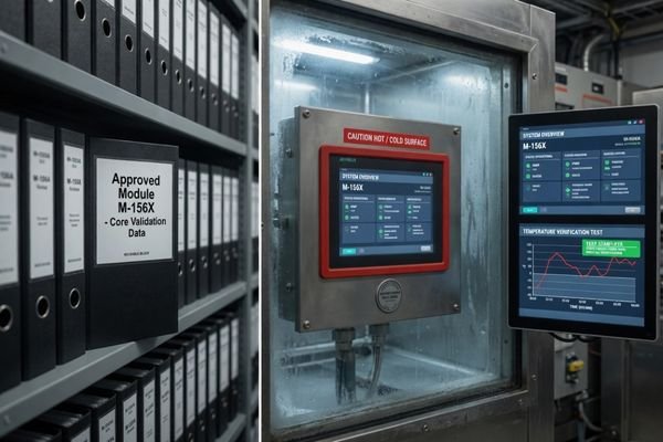
Validation reuse may include:
- interface compatibility basis;
- display timing and power-on behavior;
- brightness and optical performance reference;
- touch structure and controller tuning reference;
- mechanical outline and mounting reference;
- supplier documentation and revision history;
- previous sample or pilot test data.
However, every final device still needs equipment-level confirmation. The LCD module may be the same, but the enclosure, cable route, heat condition, grounding design, front-panel structure, and host system may be different.
Equipment-level validation should confirm:
| Validation Area | Why Equipment-Level Testing Is Still Needed |
|---|---|
| Mechanical fit | The same module may behave differently in a different enclosure or mounting structure |
| Cable routing | Cable bend, connector clearance, and assembly sequence can change by device |
| Thermal behavior | Enclosure heat and backlight power conditions may differ |
| EMI / EMC influence | Host board, cable path, shielding, and grounding can affect system behavior |
| Touch performance | Cover glass, front panel, bonding, and grounding can change touch response |
| Optical readability | Ambient light, viewing angle, and front-surface reflection differ by application |
| Power margin | Host system power capability may not be the same across equipment lines |
The right approach is controlled validation reuse. The module-level baseline can reduce repeated work, but each equipment line still requires enough system-level testing to confirm that the display works reliably in its final environment.
Connect Model Standardization with Long-Term Supply, PCN, and EOL Planning
Industrial equipment projects often require stable supply over several years. LCD module standardization should therefore support long-term model control, not only early-stage selection. A controlled display model list makes it easier to manage product changes, end-of-life notices, approved alternatives, and replacement validation.
LCD module standardization helps OEM teams manage long-term supply by linking approved models with PCN response, EOL planning, revision control, alternative evaluation, and spare parts strategy.
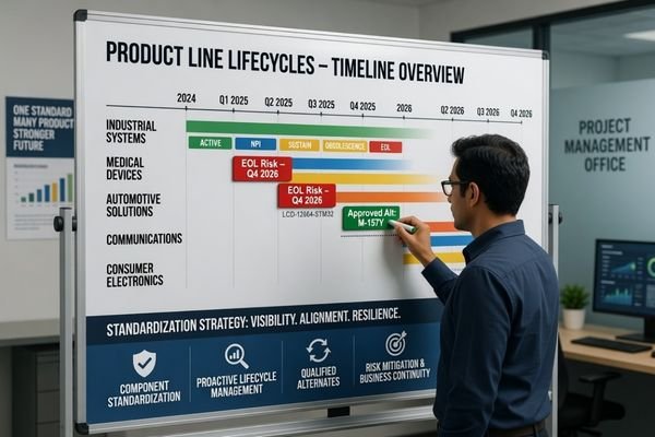
When multiple equipment lines use uncontrolled display models, every panel change can become a separate problem. One device may need a replacement panel, another may need a new controller board, and another may need a new mechanical review. If these changes are not managed through a controlled model strategy, engineering and sourcing teams may spend excessive time responding to isolated component changes.
A standardization strategy can improve long-term management in several ways:
- Approved model list: defines which LCD modules are allowed for new and existing equipment lines.
- Revision control: records approved display revisions, controller board versions, cable versions, and touch stack versions.
- PCN impact mapping: identifies which equipment lines are affected when a module supplier issues a product change.
- EOL replacement planning: defines whether the replacement should be the same model family, an approved alternative, or a custom engineering update.
- Validation reuse: allows part of the replacement review to use existing validation data where technically appropriate.
- Spare parts planning: reduces the number of display models that service teams need to manage.
Even with standardization, a replacement LCD module should not be assumed to be automatically approved across all affected equipment lines. The replacement review can be managed through a more controlled process, but each affected equipment line may still require equipment-level confirmation.
When the Same LCD Module Should Not Be Forced Across All Equipment Lines
Standardization is valuable, but over-standardization can create technical problems. A display model that works well in one equipment line may not be suitable for another if the environment, enclosure, interface, touch requirement, thermal condition, or HMI layout is different.
The purpose of LCD module standardization is to reduce unnecessary model fragmentation, not to force an unsuitable display module into every device. A controlled model family is often more practical than one identical display for all equipment lines.
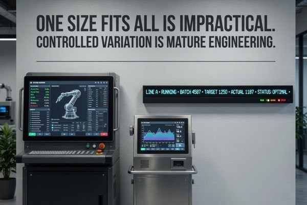
The same LCD module should not be forced across all equipment lines when there are major differences in:
- outdoor readability or sunlight exposure;
- enclosure depth, opening size, or mounting direction;
- UI aspect ratio or information layout;
- touch requirements, glove operation, wet touch, or cover glass thickness;
- operating temperature, vibration, or environmental exposure;
- host board interface and power capability;
- expected production lifecycle or service period;
- customer-specific front-panel design.
For example, an indoor HMI may use a standard industrial brightness level, while a semi-outdoor terminal may require a high-brightness configuration and different front-surface treatment. A wide machine status panel may require a bar LCD module, while an instrument front panel may require a square or round display format. These cases should not be treated as failures of standardization. They should be managed as approved variants inside the broader display model strategy.
This is where the difference between uncontrolled fragmentation and controlled variation becomes important. Fragmentation happens when every project chooses a different display without shared rules. Controlled variation happens when different module types are approved under a clear standardization framework.
How Custom LCD Module Engineering Supports Standardized Equipment Platforms
In some cases, existing industrial LCD modules may not fully match the requirements of multiple equipment lines. A standard panel may have the right size but the wrong FPC direction. Another may have a suitable display format but an unsuitable interface. A third may need a different touch structure or cover glass design to match the equipment family.
Custom LCD module engineering can support standardization by aligning interface, FPC direction, connector position, cover glass, touch structure, brightness level, controller board configuration, and mechanical outline across related equipment platforms.
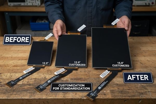
Customization should not be used to create unnecessary variants. In a standardization project, customization is most useful when it reduces system-level variation. For example, an OEM team may use custom engineering to:
- align different panels to a shared host interface;
- design a common controller board direction for several display sizes;
- adjust FPC length, cable exit direction, or connector position for common equipment assembly;
- standardize cover glass, touch sensor, or front-surface stack across related models;
- create a common mounting frame or bracket concept;
- define a stable replacement path for long-term supply.
This approach allows different equipment models to keep necessary display differences while still sharing core engineering rules. The result is not a random set of custom displays, but a more controlled LCD module platform that supports multiple industrial equipment lines.
Common Questions About LCD Module Standardization Across Equipment Lines
What is LCD module model standardization?
LCD module model standardization is the process of defining a controlled set of LCD module models, interfaces, brightness levels, mechanical structures, touch configurations, validation rules, and lifecycle controls that can be reused across multiple industrial equipment lines.
Does standardization mean using one LCD module for every device?
No. LCD module standardization does not always mean using one identical module for every device. In many industrial projects, it means creating a controlled display model family with shared specifications and approved variants for different equipment requirements.
Which LCD module specifications are most suitable for standardization?
The most suitable specifications usually include size range, resolution family, interface type, connector direction, FPC routing, brightness tier, touch type, cover glass structure, mounting method, power input, operating temperature range, validation criteria, and lifecycle control.
How does LCD module standardization reduce validation work?
LCD module standardization can reduce repeated validation work because approved display models, interfaces, touch structures, brightness tiers, mechanical directions, and documentation can share part of the module-level validation basis across equipment lines. However, each final device still requires equipment-level validation.
When should OEM teams consider custom LCD module engineering for standardization?
OEM teams should consider custom LCD module engineering when existing industrial LCD modules cannot provide enough consistency across interface, mechanical fit, cable direction, cover glass, touch behavior, brightness, controller board configuration, or lifecycle requirements for multiple equipment lines.
A Standardized LCD Module Strategy Makes Equipment Families Easier to Manage
Standardizing LCD module models across multiple industrial equipment lines is not only a cost consideration. It is an engineering and sourcing strategy for controlling model consistency, validation reuse, long-term supply, PCN response, EOL replacement, revision control, spare parts planning, and equipment-level maintainability.
A practical standardization plan does not force every device to use the same display. It defines a controlled display model family that balances shared specifications with necessary equipment-specific differences. For OEM and ODM teams managing several industrial equipment lines, this approach can make display integration more consistent, scalable, and easier to support over the full product lifecycle.
Need to standardize LCD module models across several equipment lines? Share your equipment families, target sizes, interface requirements, brightness tiers, touch needs, mechanical constraints, annual volume, lifecycle expectations, and current display model list. LCD Module Pro can help review whether a standard, modified, or custom module family is more suitable.
✉️ info@lcdmodulepro.com
🌐 https://lcdmodulepro.com/
-
"11 Ways to Manage Supply Chain Complexity", https://www.netsuite.com/portal/resource/articles/erp/supply-chain-complexity.shtml. A U.S. Department of Commerce report finds that part-number proliferation can raise supply-chain management costs by up to 20% due to increased interface and replacement-path complexity. Evidence role: statistic; source type: government. Supports: Over time, the company may need to manage too many display part numbers, too many interface variations, and too many replacement paths.. Scope note: Percentage is an industry average and may vary by sector and company size. ↩
-
"The 5 Stages of The Average Equipment Lifecycle – Asset Panda", https://www.assetpanda.com/resource-center/blog/what-is-the-average-equipment-lifecycle/. This reference describes that industrial machinery typically remains in service for 10–20 years due to extended design validation, maintenance requirements, and regulatory compliance processes. Evidence role: general_support; source type: encyclopedia. Supports: Industrial equipment often has a long product lifecycle. Scope note: Lifecycle durations vary widely by industry sector and equipment type. ↩
-
"(PDF) Platform driven development of product families – ResearchGate", https://www.researchgate.net/publication/4868917_Platform_driven_development_of_product_families_Linking_theory_with_practice. Ulrich and Eppinger (2015) describe product platform–based model families as a foundational element of robust standardization strategies, enabling controlled management of variant differences. Evidence role: expert_consensus; source type: paper. Supports: A strong standardization strategy organizes these differences into a controlled model family.. Scope note: General framework; practical implementation details vary by industry and product complexity. ↩
-
"Custom Resolution Utility (CRU) – Monitor Tests", https://www.monitortests.com/forum/Thread-Custom-Resolution-Utility-CRU. The graphics display resolution entry documents how standardized pixel dimensions (e.g., 1920×1080) enable reuse of UI layouts and related software across devices. Evidence role: general_support; source type: encyclopedia. Supports: Shared resolution levels help UI and software reuse.. Scope note: Discusses general computing displays and may not directly address industrial HMI contexts. ↩