Designing a display module for marine, port, and outdoor equipment is more demanding than selecting a standard screen for general outdoor use. Marine environments combine strong sunlight, water reflection, moisture, salt exposure, temperature changes, vibration, and long equipment lifecycles. If these factors are not considered together, the display may remain functional in a basic test but become unreliable after real field installation.
Marine display projects require a system-level approach. Reliable performance depends on visibility, optical design, environmental protection, thermal behavior, mechanical integration, touch usability, and long-term supply stability—not brightness alone.
This article focuses on LCD module selection and integration for marine, port, and outdoor equipment. It does not focus on complete certified navigation display systems. For final equipment that requires marine type approval, IEC-related testing, or other project-specific compliance requirements, the LCD module should be selected together with the enclosure, power design, connector strategy, EMC plan, and system-level validation process.
For equipment manufacturers, the display should be treated as part of the whole device design1, not as an isolated LCD specification. LCD Module Pro supports marine and outdoor equipment projects at the module level, including brightness selection, optical bonding, cover glass design, touch integration, interface matching, mechanical review, and long-term supply planning. The goal is to help equipment developers confirm a display direction before the enclosure, prototype, and validation plan are locked.
Why Marine Display Projects Are More Demanding Than Standard Outdoor Displays
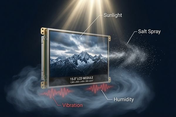
Marine display projects are more complex than standard outdoor display applications because the marine environment creates several risks at the same time. A display installed in marine, port, or coastal outdoor equipment may need to handle strong sunlight, reflection from water or metal surfaces, humidity, salt exposure, vibration, and large temperature changes within the same product design.
Display issues in marine environments are usually caused by multiple environmental and mechanical factors acting together, not by a single weak specification. A successful marine display solution should be evaluated as a complete module-level system.
A common mistake is to evaluate only one specification, such as brightness or operating temperature. For example, a high-brightness LCD may still become difficult to read if surface reflection is too strong. A wide-temperature panel may still fail prematurely if the backlight heat cannot escape from a sealed enclosure. A rugged mechanical frame may still create reliability problems if connector placement, cable routing, or sealing design is not considered.
In marine applications, these factors often compound each other. Sunlight increases internal heat. Heat accelerates material aging.1 Moisture may become trapped inside an air gap or around connectors. Salt exposure can accelerate corrosion of metal parts and electrical contacts. Vibration may add stress to cables, FPCs, mounting points, and connectors.
This is why marine display projects should be reviewed from the beginning as an integrated display module design, rather than a simple screen replacement task.
Sunlight Readability Is Not Solved by Brightness Alone
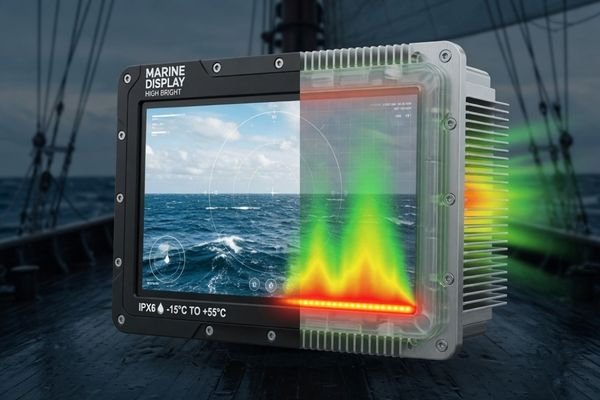
For marine and outdoor equipment, sunlight readability is one of the most visible requirements. High brightness is important, but increasing the backlight alone does not guarantee that the screen will remain readable in real marine conditions.
Effective sunlight readability depends on brightness, contrast, reflection control, optical bonding, surface treatment, viewing angle, and thermal stability. A display with high nit value can still look washed out if the optical stack is not designed for strong ambient light.
Marine environments often create stronger visibility problems than ordinary outdoor sites. Water surfaces, white vessel structures, metal panels, and open sky exposure can all increase glare and reflection. In these conditions, the screen must not only emit more light, but also reduce the amount of reflected ambient light reaching the viewer.
For exposed outdoor marine applications, high brightness LCD modules are often required. However, the final brightness target should be confirmed based on the installation angle, expected sunlight exposure, cover glass structure, optical bonding, surface coating, and heat dissipation limits.
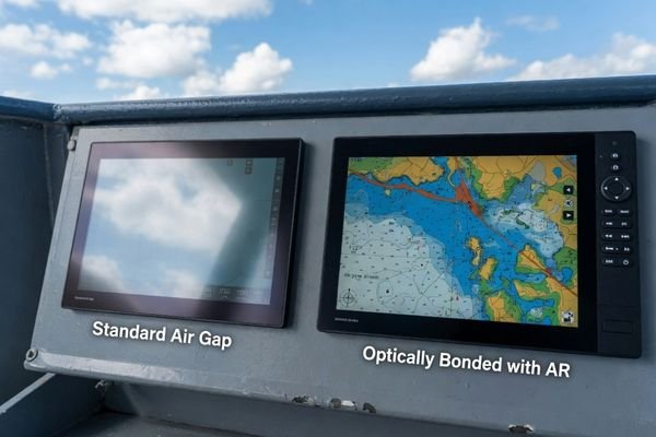
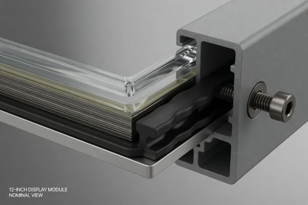
Optical bonding can help reduce internal reflection by eliminating the air gap between the cover glass and LCD. Anti-reflective coating can reduce surface reflection, while anti-glare treatment can help scatter harsh reflections from sunlight or water. In many marine equipment projects, brightness, bonding, cover glass, AG/AR treatment, and thermal design should be evaluated together before the display specification is finalized.
In marine and outdoor LCD module projects, LCD Module Pro typically reviews brightness together with optical bonding, AG/AR surface treatment, cover glass structure, viewing angle, power consumption, and thermal limits instead of selecting the backlight only by nit value. This helps avoid the common problem of choosing a very bright display that still performs poorly because reflection or heat was not properly addressed.
Reflection, Moisture, and Salt Exposure Are Core Marine Display Risks
Marine environments are not only bright; they are also humid, reflective, and corrosive. Reflection, moisture, and salt exposure are three of the most important risks that separate marine display applications from many standard outdoor display projects.
Reflection affects visibility, moisture affects optical and electrical stability, and salt exposure accelerates corrosion. These risks should be considered together because one weak point can reduce the reliability of the whole display system.
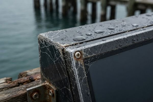
Reflection can make the display difficult to read even when the backlight is bright enough.2 Moisture may cause fogging, contamination, touch malfunction, or electrical instability if it reaches sensitive areas. Salt exposure can accelerate corrosion around metal frames, connectors, FPC contacts, screws, brackets, and enclosure edges.
The LCD module is only one part of the final environmental protection design. Final reliability also depends on the enclosure sealing, connector protection, cable entry design, ventilation strategy, material selection, and installation method.
| Risk | Impact on Display Module | Recommended Design Direction |
|---|---|---|
| Reflection | Lower contrast and reduced readability under sunlight, water reflection, or metal surface reflection. | Optical bonding, anti-reflective treatment, anti-glare treatment, high-contrast panel selection, and suitable installation angle. |
| Moisture | Fogging, optical degradation, connector instability, touch malfunction, or contamination inside the display structure. | Bonding structure review, cover glass design, equipment-level sealing, protected connector strategy, and moisture control planning. |
| Salt Exposure | Corrosion around metal parts, connectors, FPC contacts, brackets, screws, and enclosure interfaces. | Corrosion-resistant material selection, protected electrical interfaces, equipment-level sealing, and suitable coating or protection for related boards where applicable. |
For marine and outdoor projects, the display module should be reviewed together with the final equipment structure. A well-selected LCD panel can still become unreliable if the enclosure, connectors, or cable routing do not match the real environment.
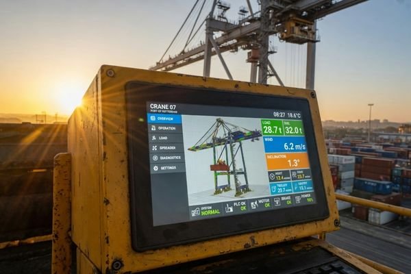
For applications such as vessel equipment, port systems, offshore monitoring terminals, and coastal outdoor devices, marine and outdoor equipment display solutions should be evaluated as part of the complete equipment design.
Temperature Change and Backlight Heat Affect Display Stability
Marine displays may face direct sunlight during the day, lower temperatures at night, and limited airflow inside sealed or semi-sealed equipment. At the same time, high-brightness backlights generate additional heat, which can affect LCD performance and long-term stability.
A stable marine display module must manage both external temperature changes and internal backlight heat. Poor thermal design can reduce brightness stability, shorten backlight lifetime, and increase the risk of premature failure.
Thermal design should not be treated as an afterthought. In a sealed enclosure, heat from the backlight, driver board, power circuit, and surrounding electronics may accumulate. If the heat cannot be transferred away from the LCD module, the display may suffer from luminance reduction, dark spots, panel stress, shorter LED lifetime, or unstable operation.
For example, some exposed outdoor applications may require 1000 nits or higher brightness. However, higher brightness usually means higher backlight power and more heat.3 If the project requires a 1500-nit or 2000-nit backlight, the thermal path from the LED backlight to the metal frame, equipment chassis, or external enclosure becomes critical.
Temperature range should also match the real operating environment. A wide-temperature LCD may be needed for equipment used in cold mornings, hot daytime sunlight, or enclosed outdoor cabinets. The final design should consider:
- operating temperature range
- storage temperature range
- backlight heat generation
- heat dissipation path
- enclosure airflow
- metal frame or chassis design
- brightness derating strategy
- long-term backlight lifetime
For high-brightness marine projects, LCD Module Pro can review the backlight power, brightness target, heat path, enclosure space, and expected operating environment together before the module specification is finalized. This type of review is especially important when the display will be installed in a sealed housing with limited airflow.
For sealed marine or outdoor equipment, an early module-level engineering review can help identify thermal risks before the prototype design is locked.
Mechanical Integration Matters in Marine and Port Equipment
A marine LCD module is not only an electronic component. It is also part of a larger equipment structure that may face vibration, movement, limited internal space, sealed installation, and long-term mechanical stress.
Mechanical integration affects whether the display module can be installed securely, connected reliably, protected properly, and maintained efficiently throughout the equipment lifecycle.
Mechanical problems often appear late in a project if the display is selected only by size, resolution, and brightness. A module may technically meet the optical requirements but still create integration problems if the FPC direction conflicts with the enclosure design, the connector position is inaccessible, or the mounting structure cannot handle vibration.
Important mechanical factors include:
- outline dimensions
- active area and viewing area
- module thickness
- mounting method
- cover glass size and support
- FPC exit direction
- connector position
- cable routing
- screw hole location
- gasket and sealing area
- backlight structure
- service and replacement access
In marine and port equipment, the mechanical design should also account for vibration, shock, equipment movement, and long-term cable stress. The goal is not only to make the display fit, but to make the display remain stable after repeated operation, transportation, installation, and maintenance.
During custom LCD module evaluation, LCD Module Pro normally checks outline dimensions, active area, FPC direction, connector position, mounting structure, cover glass support, cable routing, and service access against the customer’s enclosure design. This helps identify integration risks before the mechanical structure becomes difficult or expensive to change.
When standard modules cannot match the mechanical structure of the final equipment, custom LCD module engineering may be required to adjust the cover glass, FPC direction, interface position, backlight structure, bonding method, or mechanical outline.
Touch Operation Must Match Wet, Gloved, and Outdoor Use
Touchscreens are common in modern marine and outdoor equipment, but marine conditions can make touch performance less stable than in indoor applications. Wet hands, gloves, water droplets, salt residue, vibration, and surface contamination may all affect touch operation.
A touch panel used in marine equipment must be matched to the actual operating environment. Without proper selection or tuning, the display may suffer from false touches, reduced sensitivity, unstable response, or poor usability in wet or gloved operation.
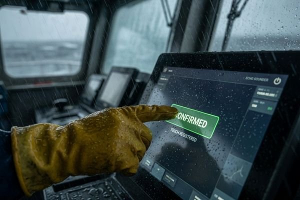
Projected capacitive touch is widely used because it supports modern interface design and multi-touch operation. However, standard PCAP settings may not be suitable for marine environments. Water droplets can sometimes be interpreted as touch input.4 Thick gloves may reduce sensitivity. A thicker cover glass can improve protection but may also require touch controller tuning.
For marine applications, the touch solution should consider:
- wet hand operation
- glove operation
- water rejection
- cover glass thickness
- touch controller tuning
- bonding structure
- surface contamination
- vibration interference
- operating temperature
- expected user behavior
In marine LCD module projects, LCD Module Pro can evaluate the touch method together with the cover glass thickness, bonding structure, operating environment, and user interaction requirements. Depending on the application, the solution may involve PCAP tuning, water rejection settings, glove operation support, or a different touch technology.
In some harsh or function-focused industrial applications, resistive touch may still be considered because it can work with gloves and physical pressure. The best choice depends on the final equipment use case, user interaction method, environmental exposure, and durability requirements.
The key is not to choose touch technology based only on appearance or cost. It should be selected as part of the complete marine LCD module design.
Long-Term Supply Stability Is Critical for Marine Equipment
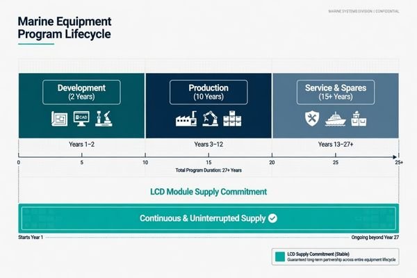
Marine and outdoor industrial equipment usually has a much longer lifecycle than consumer electronics. A display module selected during development may need to remain available for years of production, maintenance, and spare part support.
For marine equipment manufacturers, LCD module lifecycle stability can be as important as optical or electrical performance. A display change may trigger redesign, revalidation, mechanical updates, firmware adjustments, and after-sales support risks.
If an LCD module becomes unavailable or changes in size, brightness, interface, connector position, backlight design, or mechanical structure, the equipment manufacturer may need to redesign the enclosure, update firmware, revalidate the system, and manage compatibility risks. This can create higher long-term cost than the initial display price difference.
For marine and industrial outdoor projects, it is important to evaluate:
- expected product lifecycle
- LCD panel availability
- interface consistency
- mechanical compatibility
- backlight specification stability
- replacement planning
- change notification process
- second-source or alternative module strategy
- spare part requirements
LCD Module Pro considers lifecycle and replacement planning during marine and outdoor display module evaluation. This does not mean every project has the same supply plan, but it does mean that availability, specification consistency, replacement direction, and change control should be discussed before the module is selected for long-term equipment programs.
A reliable display module strategy should support long-term supply planning, specification consistency, and change control. This is especially important for equipment that will be installed in remote sites, vessels, port facilities, offshore systems, or outdoor industrial environments where maintenance is more difficult.
How to Choose the Right LCD Module for Marine Equipment
Selecting the right LCD module for marine equipment should start with the application environment, not with a list of available screens. The best solution is usually the one that balances visibility, environmental reliability, mechanical fit, touch usability, thermal behavior, and long-term supply.
A suitable marine LCD module should be selected through a complete application review. The selection process should confirm how and where the equipment will be used before finalizing the display specification.
The following table summarizes the key factors that should be reviewed during marine LCD module selection:
| Selection Factor | Why It Matters | What to Confirm |
|---|---|---|
| Brightness | Affects outdoor readability under sunlight. | Target nits, viewing angle, sunlight exposure, installation position. |
| Optical Bonding | Reduces internal reflection and may help lower fogging risk inside the display stack. | Bonding requirement, cover glass structure, optical performance target. |
| Surface Treatment | Controls glare and front-surface reflection. | AG, AR, or combined treatment based on viewing conditions. |
| Temperature Range | Affects LCD response, backlight lifetime, and long-term reliability. | Operating temperature, storage temperature, thermal path, enclosure airflow. |
| Touch Method | Determines usability in wet, gloved, or contaminated environments. | PCAP tuning, glove mode, water rejection, resistive touch option if needed. |
| Interface Type | Affects compatibility with the host system. | LVDS, eDP, HDMI, MIPI, or other project-specific interface requirements. |
| Mechanical Design | Determines whether the module fits and remains stable in the final equipment. | Outline size, thickness, mounting, FPC direction, connector position, cable routing. |
| Lifecycle | Reduces redesign and spare part risk. | Availability, replacement plan, specification consistency, change control. |
| Certification Plan | Ensures the module selection supports final equipment validation. | Marine type approval, EMC plan, enclosure design, connector strategy, system-level testing. |
When reviewing a marine LCD module project, LCD Module Pro usually starts from the application environment, installation method, interface requirement, touch operation, mechanical constraints, thermal conditions, and lifecycle expectation before recommending a standard, modified, or custom module solution. This approach helps avoid choosing a display only because it matches the size or brightness requirement on paper.
If the project involves marine, port, or coastal outdoor equipment, it is also useful to compare available industrial LCD module options before deciding whether a standard module, modified module, or fully custom display module is more suitable.
When Standard LCD Modules May Not Be Enough
A standard LCD module may be suitable for protected indoor or semi-outdoor marine equipment. However, exposed or demanding marine applications may require a customized module-level solution.
Customization should be considered when:
- the standard size does not fit the enclosure
- the display needs higher brightness or a specific backlight lifetime
- optical bonding is required
- AG or AR cover glass is needed
- wet hand or glove touch operation must be supported
- the FPC direction or connector position conflicts with the enclosure
- a wide-temperature LCD is required
- the project needs a specific interface or controller configuration
- long-term supply and replacement planning are important
- the final equipment has a specific certification or validation plan
In these cases, early display module evaluation can reduce redesign risk and help the equipment manufacturer confirm the display direction before tooling, enclosure design, and prototype validation progress too far.
Common Questions About Marine LCD Module Selection
What brightness is needed for a marine display?
The required brightness depends on sunlight exposure, reflection level, installation angle, viewing distance, cover glass, optical bonding, and surface treatment. Marine applications often need high-brightness LCD modules, but real readability should be judged by the complete optical design, not only by the nit value.
Is optical bonding necessary for marine LCD modules?
Optical bonding is not mandatory for every marine project, but it is often useful when the display needs better sunlight readability, reduced internal reflection, improved structural stability, and lower fogging risk inside the display stack.
Can standard LCD modules be used in marine equipment?
Standard LCD modules may be used in protected indoor or semi-outdoor marine equipment. However, exposed outdoor, deck, port, control panel, or harsh-environment applications usually require additional evaluation for brightness, temperature range, touch operation, bonding, sealing, mechanical integration, and long-term supply.
What causes marine displays to fail?
Marine display failures may come from poor sunlight readability, overheating, moisture, salt exposure, vibration, connector instability, unsuitable touch design, insufficient sealing, mechanical mismatch, or unstable long-term LCD module supply.
What information is needed to start a custom marine LCD module project?
A custom marine LCD module project usually requires screen size, resolution, brightness target, interface type, touch requirement, installation position, operating temperature, enclosure structure, cover glass design, bonding requirement, expected lifecycle, and any final equipment certification plan. These details help the engineering team evaluate whether a standard, modified, or custom LCD module is more suitable.
Reliable Marine Display Solutions Start with Module-Level Design
Reliable marine display performance is not achieved by choosing the brightest screen alone. It depends on readability, reflection control, moisture protection, salt exposure resistance, thermal stability, vibration tolerance, touch usability, mechanical integration, and long-term availability.
For marine, port, and outdoor equipment manufacturers, early LCD module evaluation can reduce redesign risk before the prototype is locked. Brightness, bonding, cover glass, touch method, interface, mechanical constraints, thermal behavior, and lifecycle planning should be reviewed together before finalizing the display specification.
LCD Module Pro supports marine and outdoor equipment projects through module-level display evaluation, including brightness selection, optical bonding, surface treatment, touch integration, interface matching, mechanical review, and long-term supply planning. The purpose is not only to provide a display module, but to help equipment manufacturers confirm whether the selected display direction can match the real operating environment and product lifecycle.
Need a display module for marine, port, or outdoor equipment?
Share your display size, brightness target, interface, touch requirement, installation environment, and mechanical constraints with our engineering team for a module-level review.
Start Your Marine Display Module Project
✉️ info@lcdmodulepro.com
🌐 https://lcdmodulepro.com/
-
"System Integration – SEBoK", https://sebokwiki.org/wiki/System_Integration. SEBoK explains that system integration treats subsystems as part of the overall product design. This supports the view that display modules should be considered within the full device architecture, not only as isolated LCD specifications. Scope note: General systems framework, not display-specific requirements. ↩ ↩
-
"What Makes a Monitor Sunlight Readable? – AbraxSys", https://www.abraxsyscorp.com/what-makes-a-monitor-sunlight-readable/. Optical studies show that reflections can reduce LCD contrast and readability, even with high backlight brightness. Scope note: Results may vary by panel type, surface treatment, and outdoor conditions. ↩
-
"LED Brightness VS Power/Current – All About Circuits Forum", https://forum.allaboutcircuits.com/threads/led-brightness-vs-power-current.74332/. LED backlight discussions note that higher brightness usually requires more drive current, increasing power use and heat. Scope note: Actual power and heat output depend on LED efficiency and backlight design. ↩
-
"Capacitive Touch Waterproof Guide: Rain/Wet/Fog Solutions – MAXEN", https://maxen-lcddisplay.com/capacitive-touch-waterproof-wet-hand-rain-fog/. Touchscreen studies show that water droplets can interfere with projected capacitive sensors and cause false touches. Scope note: Real-world behavior depends on sensor design, firmware, and marine conditions. ↩