When an LCD display module shows banding, diagnosing the bit-depth settings should be one of the first engineering checks. In practical LCD module integration, this issue is rarely caused by the panel alone. In most cases, it reflects a mismatch or limitation somewhere in the full display chain, including the source content, host output, interface configuration, or panel-side processing.
Diagnosing banding related to bit-depth requires a step-by-step isolation process across the full signal path. The most effective method is to verify the source content, host system output, display interface, and panel behavior one stage at a time, using controlled test patterns and confirmed configuration settings to identify where color precision is being reduced.
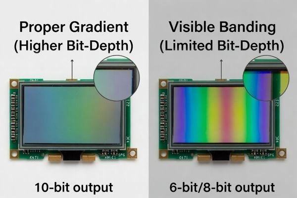
Based on my LCD display module integration work at LCD Module Pro, banding is one of the most common visual issues reported during prototype validation. Many teams initially assume the panel is low quality or defective, but that is often not the real cause. A 10-bit-capable LCD module can still show visible banding1 if the graphics processor outputs only 8-bit color, if the operating system or driver is limiting output depth, or if the display interface is not configured correctly.
A reliable diagnosis requires isolating variables one by one across the display signal chain. Instead of treating the LCD module as a standalone part, it should be evaluated as one element within a larger system where source data, signal processing, output configuration, and interface timing all affect the final result. With a structured engineering approach, banding can be diagnosed objectively rather than judged only by subjective visual complaints.
What Does Banding Look Like on an LCD Display Module?
Before diagnosing bit-depth settings, the first step is to confirm that the visible artifact is true color banding and not another display issue with a similar appearance.
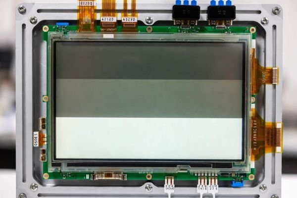
Banding appears as visible, step-like transitions in an area that should display a smooth and continuous gradient of color or brightness. It is most obvious in soft grayscale ramps, large color gradients, dark UI shadows, and other scenes with subtle tonal transitions.
When I troubleshoot display problems in the field, I always begin by confirming the symptom with controlled test patterns. This is important because several display artifacts can look similar at first glance but require very different corrective actions.
Visual Characteristics of Banding
The most recognizable sign of banding is the presence of visible contour lines or abrupt tonal steps in a gradient. Instead of a smooth transition from light gray to dark gray, for example, the image may appear as a sequence of distinct gray layers. This happens when the effective number of reproducible tonal levels is not sufficient for the displayed content. In general, the fewer usable shade steps available in the signal path, the more noticeable the banding becomes.
Distinguishing Banding from Other Artifacts
True bit-depth-related banding2 should be distinguished from other image quality problems. Poor backlight uniformity may create bright or dark patches that can be mistaken for tonal stepping, especially in darker scenes. Compressed image files may also introduce blocking or posterization that resembles banding but originates in the image data itself rather than the display chain. For accurate diagnosis, it is best to use mathematically clean, uncompressed gradient patterns so that any visible stepping can be attributed more confidently to the system rather than to the source file.
What Are the Most Common Bit-Depth-Related Causes of Banding?
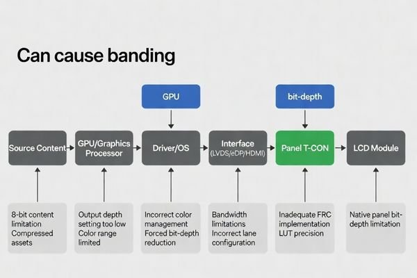
Banding is typically a system-level problem caused by lost or reduced color precision somewhere between the source content and the LCD pixels.
The most common causes of banding include a mismatch between source bit-depth and panel capability, GPU or operating system settings that force lower output depth, interface bandwidth or timing limitations, and panel-side processing such as Frame Rate Control (FRC) that does not fully smooth the gradient.
In engineering practice, I usually review the full signal path with a fixed checklist. This prevents unnecessary panel replacement and helps identify the actual stage where tonal precision is being reduced.
- Source and Application Limitations: The issue may begin with the content itself. An 8-bit image or compressed visual asset will still show banding even on a higher-capability LCD module. Some operating systems, applications, or graphics frameworks may also process the image internally at a lower bit-depth.
- Graphics Processor and Driver Settings3: This is one of the most frequent root causes. The graphics processor may default to 8-bpc output, and many systems require manual configuration to enable 10-bpc output. If banding disappears on a known-good high-bit-depth source, the host system is usually the likely cause.
- Interface Configuration: The display interface must be configured to carry the intended color precision correctly. LVDS, eDP, HDMI, or other interfaces can reduce effective bit-depth if timing, mapping, or bandwidth allocation is incorrect.
- Panel-Side Processing: Some LCD modules use
8-bit + FRCto simulate higher bit-depth. In many applications this works well, but panel implementation, content type, and timing quality all influence whether the result is visually smooth enough.
In many prototype-stage cases, the root cause is found in output configuration rather than in the LCD module itself. That is why diagnosing bit-depth settings should always begin upstream before drawing conclusions about panel quality.
How Do You Isolate Whether the Problem Comes from the Source, Interface, or Panel?
The most reliable way to diagnose banding is to isolate the display chain in a controlled sequence. The key rule is simple: change only one variable at a time.
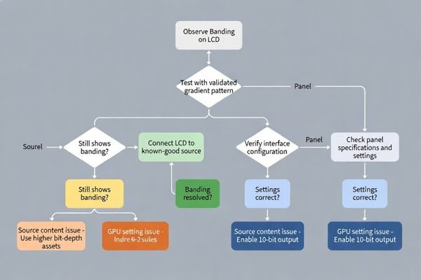
To isolate the source of banding, test the same LCD module with a known-good reference source and validated gradient patterns. If the banding disappears, the problem is usually in the original host system or output configuration. If it remains across validated sources and settings, panel-side behavior or direct interface configuration should be reviewed more closely.
When a customer reports banding, this is the structured process I usually recommend:
| Isolation Step | Action | Interpretation of Result |
|---|---|---|
| 1. Change the Source Content | Display a high-quality, uncompressed gradient test pattern4 on the target system. | If banding disappears, the original content or rendering pipeline was the cause. If it remains, continue to the next stage. |
| 2. Change the Host System | Connect the same LCD module and cable to a known-good PC, development board, or signal generator that has validated high-bit-depth output. | If banding disappears, the original host GPU, OS, application, or output settings are the likely cause. |
| 3. Change the Interface or Cable | Test with another validated cable or switch interface type if the system supports it. | If the problem disappears, the original cable, interface path, or interface configuration may have been limiting signal quality or effective color depth. |
| 4. Analyze the Panel Side | Review the same panel under known-good conditions if the issue remains. | If banding persists across validated sources and interfaces, panel-side FRC behavior, T-CON processing, gamma settings, or LUT behavior should be reviewed. |
This sequence reduces wasted effort and keeps the diagnosis evidence-based. If banding disappears on a known-good source, the host system is the likely root cause. If it persists across validated sources, panel-side processing should be reviewed in more detail. If you need help validating gradient test patterns or reviewing the display signal path, feel free to contact my team at info@lcdmodulepro.com.
Which Test Methods and Tools Help Confirm Bit-Depth Settings?
Visual inspection is a useful starting point, but a proper engineering diagnosis should combine visual confirmation with measurable configuration checks.
The most effective way to confirm bit-depth settings is to combine standardized gradient test patterns with software and hardware verification tools. This typically includes grayscale ramps, RGB gradients, GPU output setting checks, EDID review, and register-level inspection in embedded systems.
In actual display debugging, I rely on both visual test patterns and configuration-level confirmation. This matters because a system may appear to run in a higher-quality mode while the actual output path is still limited to a lower bit-depth.
Visual Test Patterns
Controlled test patterns are essential because they expose banding more clearly than normal user-interface content.
- Smooth Grayscale Ramp: A full transition from black to white is the standard test for luminance stepping and tonal compression.
- RGB Gradient Charts: Linear gradients in red, green, and blue can reveal channel-specific limitations or mismatches in output behavior.
- Near-Black Transition Patterns: The human eye is especially sensitive to subtle transitions in dark regions, making near-black ramps very useful for detecting bit-depth limitations and gamma-related artifacts.
- Controlled UI Scenes: Interfaces with soft shadows, overlays, and gradual background transitions can help confirm whether the issue is also visible in real application conditions.
Software and Configuration Tools
A visual result should always be confirmed against actual system settings.
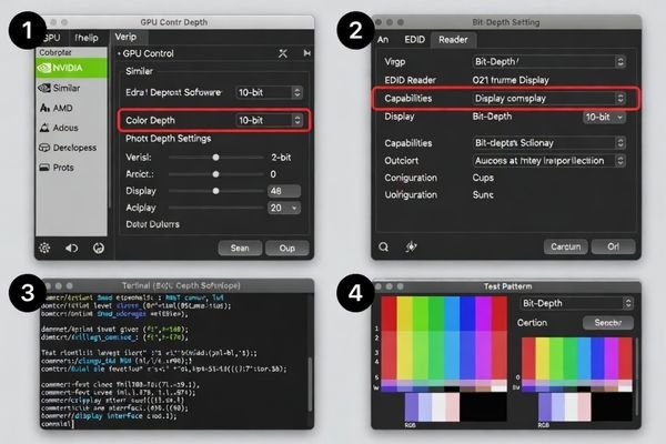
- GPU Control Panels5: On PC-based systems, NVIDIA, AMD, and Intel tools typically show the current output color depth directly, such as 8-bpc or 10-bpc.
- Operating System and Graphics Settings: Some systems may still constrain output depth even when the panel and GPU support higher values, so application and OS-level color configuration should also be reviewed.
- EDID Readers: EDID data helps confirm whether the display is properly advertising its supported formats and whether the source is likely to negotiate the intended mode correctly.
- Register Inspection in Embedded Systems: In embedded designs, engineers may need to review display controller registers, output format settings, and timing tables directly to verify the real active bit-depth.
- Interface Documentation Review: LVDS or eDP timing tables, lane mapping, and format definitions should be checked to ensure the intended signal path is actually configured for the target output precision.
This combined approach is much more reliable than visual judgment alone. A display may look acceptable under some content while still running below its intended bit-depth capability.
What Corrective Actions Reduce Banding After the Diagnosis?
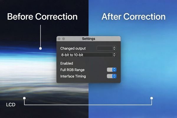
Once the actual cause of banding has been identified, corrective action should target the exact point in the signal chain where color precision is being reduced.
The right corrective action depends on the diagnosed bottleneck. Host-side issues require output setting corrections, interface-side issues require timing or mapping adjustments, and panel-side limitations may require gamma tuning, FRC review, or image-level dithering strategies.
The most effective fix is always the one matched to the verified root cause. Replacing the panel without confirming the signal path is often an expensive mistake.
- Host-Side Correction: This is the most common fix. Check the GPU control panel and confirm that output color depth is set correctly. If needed, adjust the output format and verify that the graphics pipeline is not being limited by the operating system or application framework.
- Interface-Side Correction: In embedded systems, review timing parameters, format settings, lane configuration, and bandwidth margin to ensure the intended bit-depth is transmitted correctly over LVDS, eDP, or other display links.
- Content-Side Correction: If the hardware path is limited, dithering at the source can reduce the visibility of hard band edges by breaking up abrupt tonal transitions. This does not increase true bit-depth, but it can improve perceived smoothness.
- Panel-Side Correction6: If the issue is linked to panel processing, gamma LUT behavior, or FRC implementation, panel-level optimization may be required. In these cases, it is often necessary to review module-specific settings with the LCD module supplier.
In most projects, the best results come from treating banding as a full-system integration issue rather than as a single-component defect. Once the true weak point is identified, smooth gradients and better visual performance are usually achievable with targeted adjustments.
FAQ
Does visible banding always mean the LCD module is only running in 8-bit mode?
No. Visible banding can be caused by low source quality, gamma issues, image compression, interface limits, or panel processing behavior, even when the module itself supports higher bit-depth capability.
How can I tell whether the problem is from the host system or the panel?
A practical method is to test the same LCD module with a known-good reference source and compare the results. If the banding disappears, the issue is more likely in the host graphics or output configuration.
Can interface type affect effective bit-depth performance?
Yes. The display interface and its timing configuration can affect whether the intended bit-depth data is delivered correctly, especially in embedded systems using LVDS, eDP, or other serialized links.
Is 8-bit + FRC good enough to reduce banding?
In many applications, yes. 8-bit + FRC can significantly improve gradient smoothness, but its effectiveness depends on panel implementation, content type, and viewing conditions.
What test image is most useful for diagnosing banding?
Smooth grayscale ramps, RGB gradient charts, and near-black transition images are among the most useful patterns because they expose limited tonal steps very clearly.
Can software settings alone fix banding?
Sometimes, but not always. Software-side corrections help when the issue comes from output configuration or processing settings, but hardware or panel-side limits may still require deeper engineering changes.
Conclusion
Diagnosing bit-depth settings when an LCD display module shows banding requires validating the entire display signal chain rather than assuming the panel is the only cause. In most real integration cases, banding is a symptom of lost color precision somewhere between the source content and the final display output.
At LCD Module Pro, my experience shows that a structured diagnostic method saves time, reduces unnecessary component changes, and leads to a more reliable visual result. The most effective path is to confirm the content source, verify host output settings, review interface configuration, and then evaluate panel-side behavior only after the upstream stages have been validated. Treating the LCD module as part of a full system is the key to reducing banding and achieving smooth, accurate gradients in industrial and embedded display applications.
✉️ info@lcdmodulepro.com
🌐 https://lcdmodulepro.com/
-
Understanding the causes of banding can help you diagnose and fix visual issues in LCD displays effectively. ↩
-
Exploring bit-depth-related banding will enhance your knowledge on image quality issues, helping you implement better solutions. ↩
-
Understanding graphics processor settings is crucial for achieving optimal display quality. Explore this link to enhance your knowledge. ↩
-
Learning to create effective gradient test patterns is crucial for diagnosing display issues and ensuring optimal performance. ↩
-
Investigating GPU Control Panels will help you understand how to manage color depth effectively for better visual output. ↩
-
Exploring Panel-Side Correction will provide insights into optimizing panel settings for improved image quality. ↩